Solar battery

a solar energy and battery technology, applied in the field of solar energy batteries, can solve the problems of low efficiency of methods, low efficiency of quantum dot layers, and waste of materials, and achieve the effects of reducing environmental load, high electromotive force, and excellent carrier conductivity

Inactive Publication Date: 2016-07-12
NAT INST OF ADVANCED IND SCI & TECH
View PDF7 Cites 0 Cited by
  • Summary
  • Abstract
  • Description
  • Claims
  • Application Information

AI Technical Summary

Benefits of technology

[0010]The present invention has been made in light of the aforementioned drawbacks and technical problems of the conventional designs, and an objective of the invention is to provide a silicon cluster solar battery which affords a high electromotive force and a high absorption efficiency to provide high quantum conversion efficiency and which has excellent carrier conductivity.
[0012]Embodiments of the present invention comprise a quantum dot layer having a multiple energy level structure consisting of an energy level of a valence band and an energy level of a conduction band, and intermediate energy levels located between both the bands. The quantum dot layer is composed by periodically arranging silicon quantum dots consisting of silicon clusters with an average particle diameter of 2.5 nm or less a face-to-face distance between the silicon quantum dots of 1 nm or less. The average particle diameter can be found by measuring particle diameters of the clusters in an observation area of the silicon clusters and then taking the statistical average. When the silicon clusters form up a periodic array structure, a statistical average is taken for every area for a certain period (coherent length). By setting the average particle diameter at 2.5 nm or less, the silicon cluster may have, at a surface layer thereof, a cage structure excellent in carrier conductivity and achieve an excellent quantum-conversion efficiency showing an absorption coefficient two (2) orders higher than that of polycrystalline silicon. A silicon cluster layer composed of silicon clusters can thus be made thin. Accordingly, these merits can overcome the technical problems to be solved by the present invention.
[0016]According to an embodiment of the present invention, it is possible to reduce environmental load and to use a large amount of recyclable materials because the present invention provides a P—SiN—N junction solar battery in which microscopically-defined silicon clusters (hereinafter referred to as “μ-SiN clusters”) are inserted into a silicon P—N junction. Further, according to an embodiment of the present invention, the μ-SiN cluster layer inserted into the P—N junction having a high electromotive force has an effect of providing a quantum conversion efficiency two orders higher than that of the conventional polycrystalline silicon and also has an effect of having excellent carrier conductivity resulting from the cage structure appearing on the surface layer of the μ-SiN clusters.
[0017]Furthermore, the invention attains a high conversion efficiency of over 31%, being the limiting value of the conversion efficiency of the silicon solar battery based on passivation control at the junction interface in the P—SiN—N junction utilizing graphene. Moreover, according to an embodiment of the present invention, it is possible to expect high conversion efficiency over the conventional conversion efficiency while employing a device structure involving a reduced number of production steps, and it is also possible to improve productivity, thereby meeting energy demands in the future.
[0018]Additionally, according to an embodiment of the present invention, the high quantum conversion efficiency of the μ-SiN cluster layer can attain effective quantum conversion, employing a thin layer with a thickness of 1 μm or less as the μ-SiN cluster layer, and thus, the cost of silicon materials can be sufficiently suppressed.

Problems solved by technology

The conventional nc-Si / SiO2 quantum dot layer does not meet the conditions necessary to realize high conversion efficiency of a quantum dot solar battery.
Further, a method of stacking a-Si layers and SiO2 layers in alternating fashion with a thickness of several nm for each layer and then annealing the resultant stack at a high temperature for an extended period of time requires steps equal in number to the layers to be stacked, and such method has low productivity.
Further, a solar battery obtained by alternately stacking a-Si and SiO2 / Si3N4 / SiC still also involves a technical problem in the reuse of the materials involved.
Further, in the production of silicon cluster solar batteries, materials that place a lower environmental load and are that recyclable have to be used, assuming beforehand the mass use of solar batteries from a practical point of view (technical problem 2).
Moreover, considering the present technology wherein the cost of silicon materials occupies 70% of expenses, the absorption coefficient with respect to the sunlight spectrum is an important technical issue regarding a technique for producing thinner structures of the silicon cluster solar battery.

Method used


Image

  • Solar battery
  • Solar battery
  • Solar battery

Examples


first embodiment

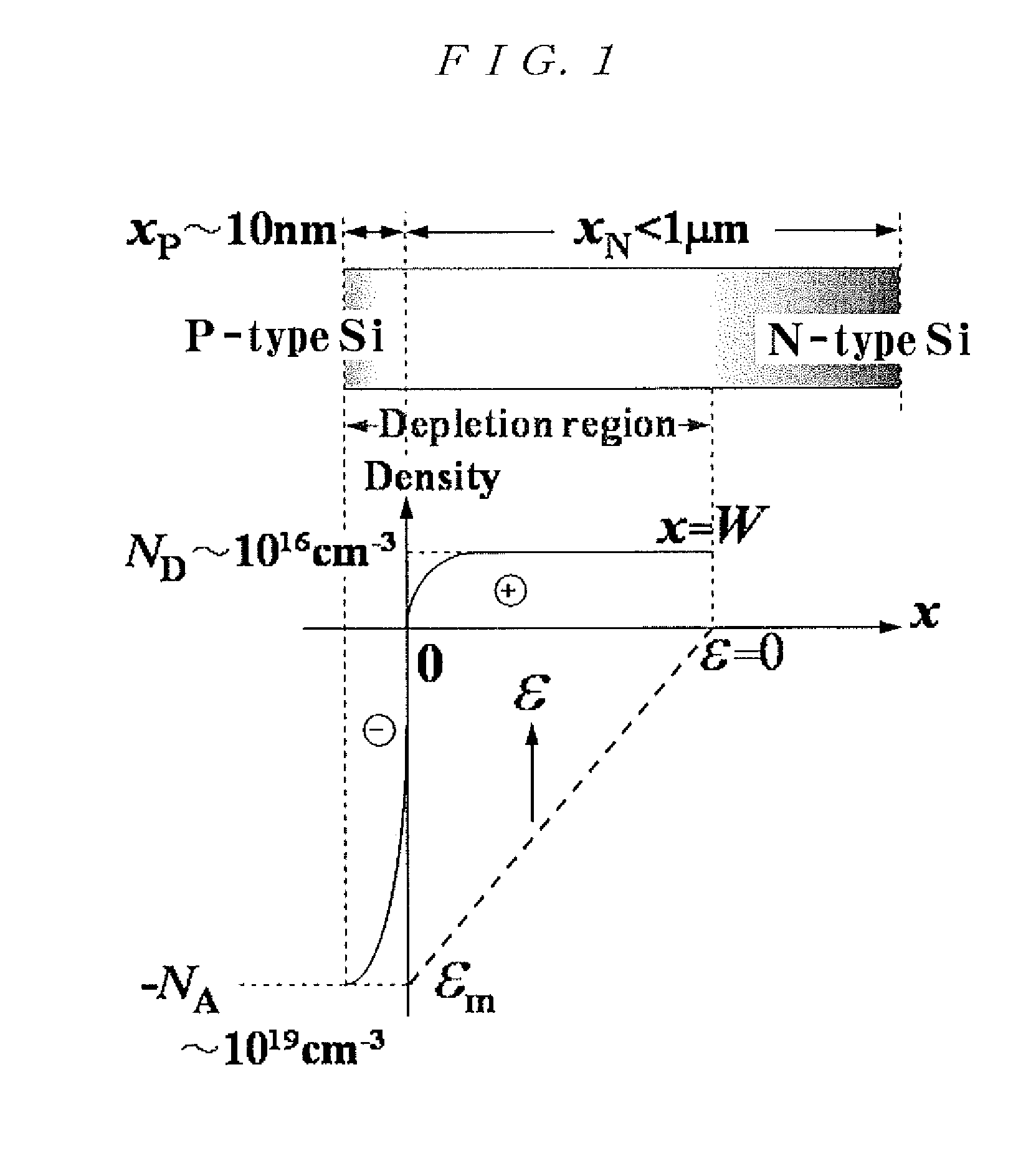
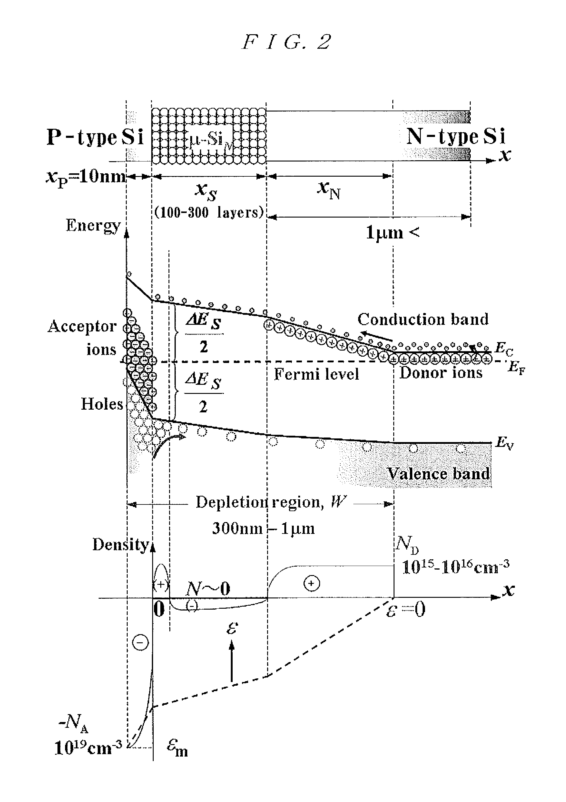
[0055]The μ-SiN cluster thin film used in the P—SiN—N junction quantum dot solar battery according to the present invention shows a superior characteristic almost satisfying the conditions necessary for the silicon quantum dot layer to function as a solar battery, which are the problems to be solved by the present invention. The P—SiN—N junction-based device structure comprising the μ-SiN cluster thin film forms the basis of the silicon cluster solar battery of the present invention.

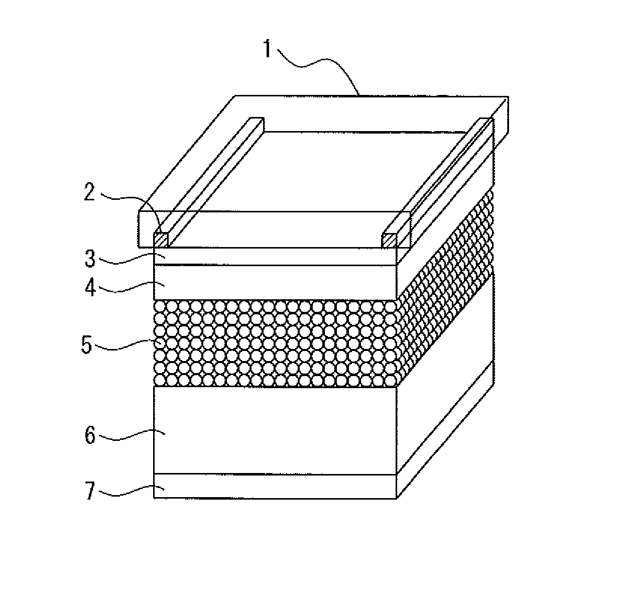
[0056]A manufacturing method of a silicon cluster solar battery will be described below in detail. The method includes the steps of: forming an electrode on a transparent substrate (step 1); forming an ITO transparent electrode (step 2); forming P-type microcrystalline silicon (step 3); forming silicon cluster (step 4); depositing N-type microcrystalline silicon (step 5); and forming a back Al earthed electrode (step 6).

[0057]As a glass substrate, ultra-precision machined high-grade glass (BDA / ABC, Nippo...

second embodiment

[0076]The second embodiment shows an example where a P—SiN—N junction utilizing graphene, as a promising passivation material for the junction interface of a silicon cluster solar battery, is included in a device design.

[0077]The production method of a silicon cluster solar battery according to the second embodiment will be explained below.

[0078]The steps of the second embodiment are the same as those of the first embodiment except that a passivation-film (graphene) deposition step is provided between the step (step 3) of depositing the P-type microcrystalline silicon and the step (step 4) of forming silicon clusters, which are the steps according to the first embodiment.

[0079]The passivation film (graphene) is formed by: producing a dispersion solution in which graphene refined from graphite by way of chemexfoliation is dispersed in methanol or in anhydrous propanol; and dropping the graphene dispersion solution on the substrate surface on which the P-type microcrystalline silicon ...


PUM

PropertyMeasurementUnit
particle diameteraaaaaaaaaa
distanceaaaaaaaaaa
thicknessaaaaaaaaaa

Abstract

Disclosed is a solar battery which: is made from a silicon semiconductor; has a high quantum-conversion efficiency; requires a small number of production steps during manufacturing; and is capable of being recycled in view of environmental load and material recycling. Specifically, a solar battery according to an embodiment of the present invention has a basic structure of a P—SiN—N junction in which minute silicon clusters are inserted in a P—N junction, and includes a quantum dot layer having a multiple energy level structure consisting of an energy level of a valence band and an energy level of a conduction band, and intermediate energy levels located between both the bands. The quantum dot layer is composed by periodically arranging silicon quantum dots consisting of silicon clusters with an average particle diameter of 2.5 nm or less and an inter-quantum-dot distance of 1 nm or less.

Description

TECHNICAL FIELD[0001]The present invention relates to a solar battery using a silicon cluster.BACKGROUND[0002]Recently, the advent of a practical solar battery excellent in conversion efficiency has been desired. Regarding the conversion efficiency of a P—N junction solar battery, the limiting value under the ideal condition under which the excitation of excitons, which absorbs sun light with a distribution of black-body radiation at a surface temperature of 6000K is balanced with radiation emitted from the deexcitation of excitons obtained as a function of a band gap Vg. The limiting value of the conversion efficiency reaches a maximum value of 31% at Vg=1.3 eV close to the band gap of silicon crystals. The maximum value is considered to be theoretical limit of the conversion efficiency of a silicon solar battery.[0003]The conversion efficiency of the silicon P—N junction solar battery is practically half or less the theoretical limit of the conversion efficiency. Examples of cause...

Claims


Application Information

Patent Timeline
Patent Type & Authority Patents(United States)
IPC IPC(8): H01L31/0264C23C14/28H01L31/028H01L31/0352H01L31/0392H01L31/06H01L31/18H01L31/075C23C14/22C23C14/04
CPCH01L31/06C23C14/048C23C14/221C23C14/228C23C14/28H01L31/028H01L31/03921H01L31/035218H01L31/075H01L31/18H01L31/1804Y02E10/547Y02E10/548Y02P70/521Y02P70/50
Inventor IWATA, YASUSHITOMITA, KANAKO
Owner NAT INST OF ADVANCED IND SCI & TECH
Why Eureka
Try Eureka