Method for producing difluoromethane
a technology of difluoromethane and difluoromethane, which is applied in the field of difluoromethane production process, can solve the problems of high corrosion of catalysts, short reaction duration, and inability to know the lifetime of catalysts, so as to reduce corrosion and yield. the effect of selectivity
- Summary
- Abstract
- Description
- Claims
- Application Information
AI Technical Summary
Benefits of technology
Problems solved by technology
Method used
Image
Examples
example 1
Preparation of Solvent-Free Ionic Liquid Catalyst
[0115]0.2 mol of SbCl5 and 0.1 mol of Emim-Cl are added. The mixture is gently heated until a homogeneous mixture is obtained. After cooling, the solid product is analyzed by nuclear magnetic resonance (NMR). The sample is dissolved in deuterated acetonitrile and analyzed by 1H, 13C and 121Sb NMR in order to establish the structure of the cation of interest. The results are presented in table 1 below.
example 2
Preparation of Ionic Liquid Catalyst with Solvent, Using a Dip Pipe
[0116]75 g of Emim-Cl are dissolved in 200 g of F-30. The item of equipment used is a glass reactor with a jacketing connected to a thermostatically controlled external bath. A thermocouple indicates the temperature during the operation. The reactor is equipped with a condenser connected to a circulation of water. A dip pipe is used as funnel to slowly add 300 g of SbCl5 at the bottom of the reactor. The operation lasts two hours but crystallization in the mixture is observed after approximately one hour. The mean rate of introduction of the SbCl5 is 150 g / h. After the end of the addition of SbCl5, the mixture has solidified. The solid is tested by NMR analysis. The results are presented in table 1 below.
examples 3 to 8
Preparation of Ionic Liquid Catalyst with Solvent, without Using a Dip Pipe
[0117]Example 2 is repeated, without the dip pipe.
[0118]The point of injection of the SbCl5 is the headspace of the reactor, above the Emim-Cl / F-30 solution. Two parameters are tested: the stirring (yes or no) and the temperature during the mixing (circulation of water in the jacketing or maintenance of a temperature which makes it possible to keep the mixture in the liquid form, between 50 and 55° C.) and the rate of introduction of the SbCl5 (fairly rapid, around 150 g / h, or else slower, at 50 g / h). A sample is withdrawn for NMR analysis.
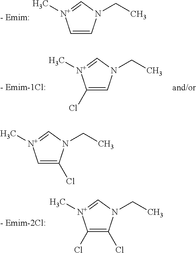
[0119]The reaction of Emim-Cl with SbCl5 produces a cationic portion and an anionic portion. The anionic portion is a halogenated antimony compound SbCl6−, mixed with neutral compounds, such as SbCl5 and SbCl3. The cationic portion is a nitrogenous ring. The NMR analysis reveals the presence of the following compounds:
[0120]
[0121]The chlorination reaction between SbCl5 and ...
PUM
| Property | Measurement | Unit |
|---|---|---|
| temperatures | aaaaa | aaaaa |
| density | aaaaa | aaaaa |
| pressure | aaaaa | aaaaa |
Abstract
Description
Claims
Application Information
 - R&D
- Intellectual Property
- Life Sciences
- Materials
- Tech Scout
- Unparalleled Data Quality
- Higher Quality Content
- 60% Fewer Hallucinations
Browse by: Latest US Patents, China's latest patents, Technical Efficacy Thesaurus, Application Domain, Technology Topic, Popular Technical Reports.
© 2025 PatSnap. All rights reserved.Legal|Privacy policy|Modern Slavery Act Transparency Statement|Sitemap|About US| Contact US: help@patsnap.com


