Single chip igniter and internal combustion engine ignition device

a single chip igniter and ignition device technology, applied in the direction of ignition safety means, machines/engines, mechanical devices, etc., can solve the problems of parasitic operation (a malfunction), increase in cost, and extremely harsh use environment, so as to reduce the operating voltage, increase noise tolerance and surge tolerance, and reduce the operating voltage of the circuit

Active Publication Date: 2016-09-20
FUJI ELECTRIC CO LTD
View PDF45 Cites 3 Cited by
  • Summary
  • Abstract
  • Description
  • Claims
  • Application Information

AI Technical Summary

Benefits of technology

[0028]Embodiments of the invention address this and other needs. Embodiments of the invention provide a single chip igniter, and an internal combustion engine ignition device including the single chip igniter, such that it is possible to realize a reduction in operating voltage, an increase in noise tolerance, an increase in surge resistance, a reduction in size, and a reduction in cost, thereby solving the heretofore described problems.
[0068]According to some embodiments of the invention, by the gate threshold voltage of an MOS transistor being a low voltage (1.5V or less) and the operating voltages of a current limiter circuit and overheat detector circuit being low voltages (1V or more), it is possible to reduce the operating voltage (1V to less than 3.5V) of a single chip igniter used in an internal combustion engine ignition device.
[0069]Also, by inserting a capacitor between gate wiring connecting a gate terminal and MOS transistor gate and ground wiring, it is possible to increase noise tolerance and surge tolerance.
[0070]Also, by configuring the current limiter circuit and overheat detector circuit of two-stage inverter circuits, it is possible to reduce the operating voltages of the circuits.
[0071]Also, as, in some embodiments, no voltage converter circuit is provided, it is possible to reduce the package size and reduce the cost in comparison with a hybrid igniter.

Problems solved by technology

As the single chip igniter 501 is used in the internal combustion engine ignition device 500, the usage environment is extremely harsh.
This is because the process is complex when a p-type MOS and n-type MOS exist together, leading to a rise in cost.
Also, when adopting a hybrid circuit (a complementary circuit, or the like) of a p-type MOS and n-type MOS, a parasitic element is formed between the two, and a parasitic operation (a malfunction) is liable to occur.
Also, as an ignition pulse (several tens of kilovolts) is generated in the immediate vicinity of the single chip igniter 501, there is concern that the single chip igniter 501 will malfunction due to noise, and the output voltage of the ECU 505 may decrease due to noise.
Because of this, the external dimensions increase, and the manufacturing cost increases.

Method used


Image

  • Single chip igniter and internal combustion engine ignition device
  • Single chip igniter and internal combustion engine ignition device
  • Single chip igniter and internal combustion engine ignition device

Examples


embodiment 1

IGBT

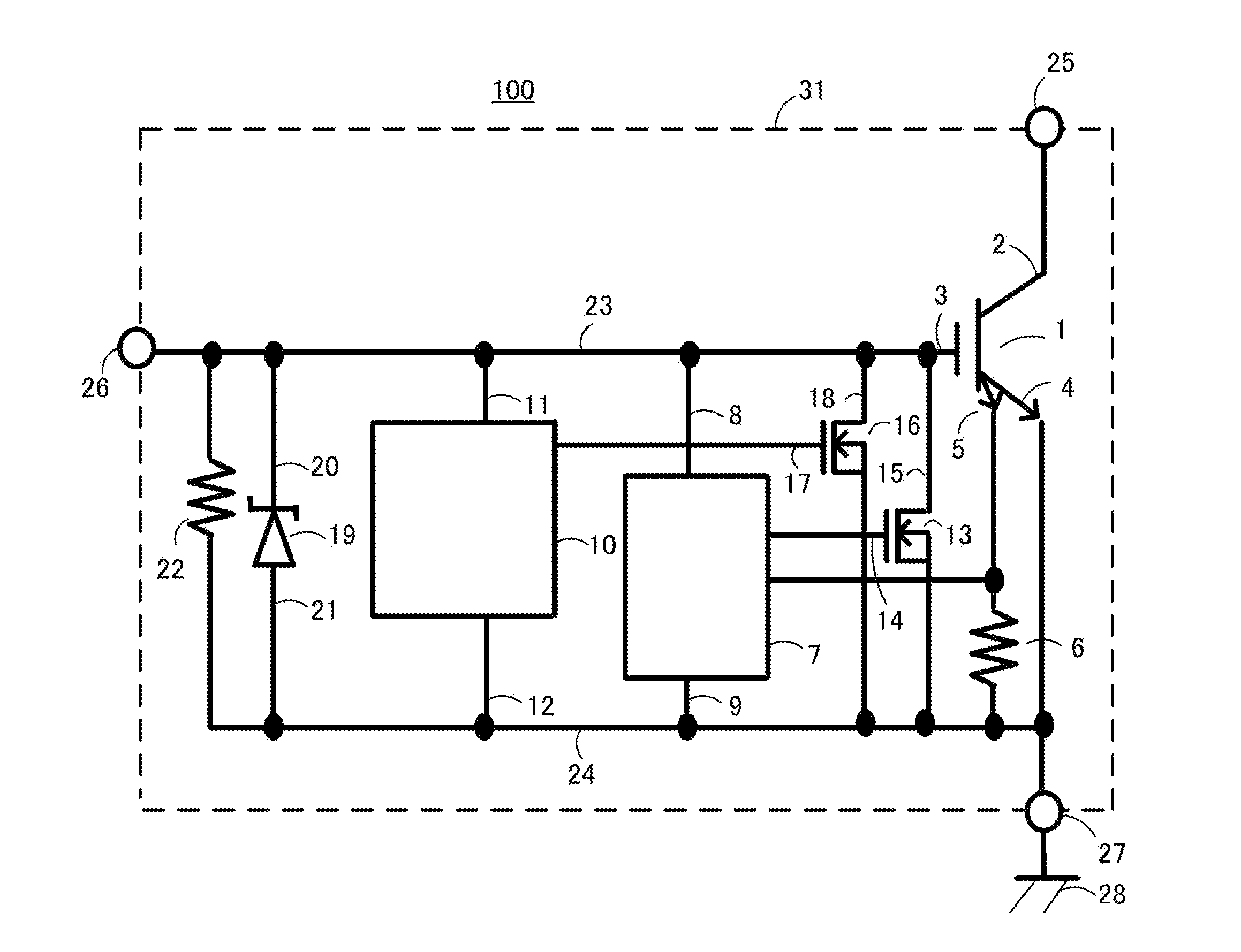
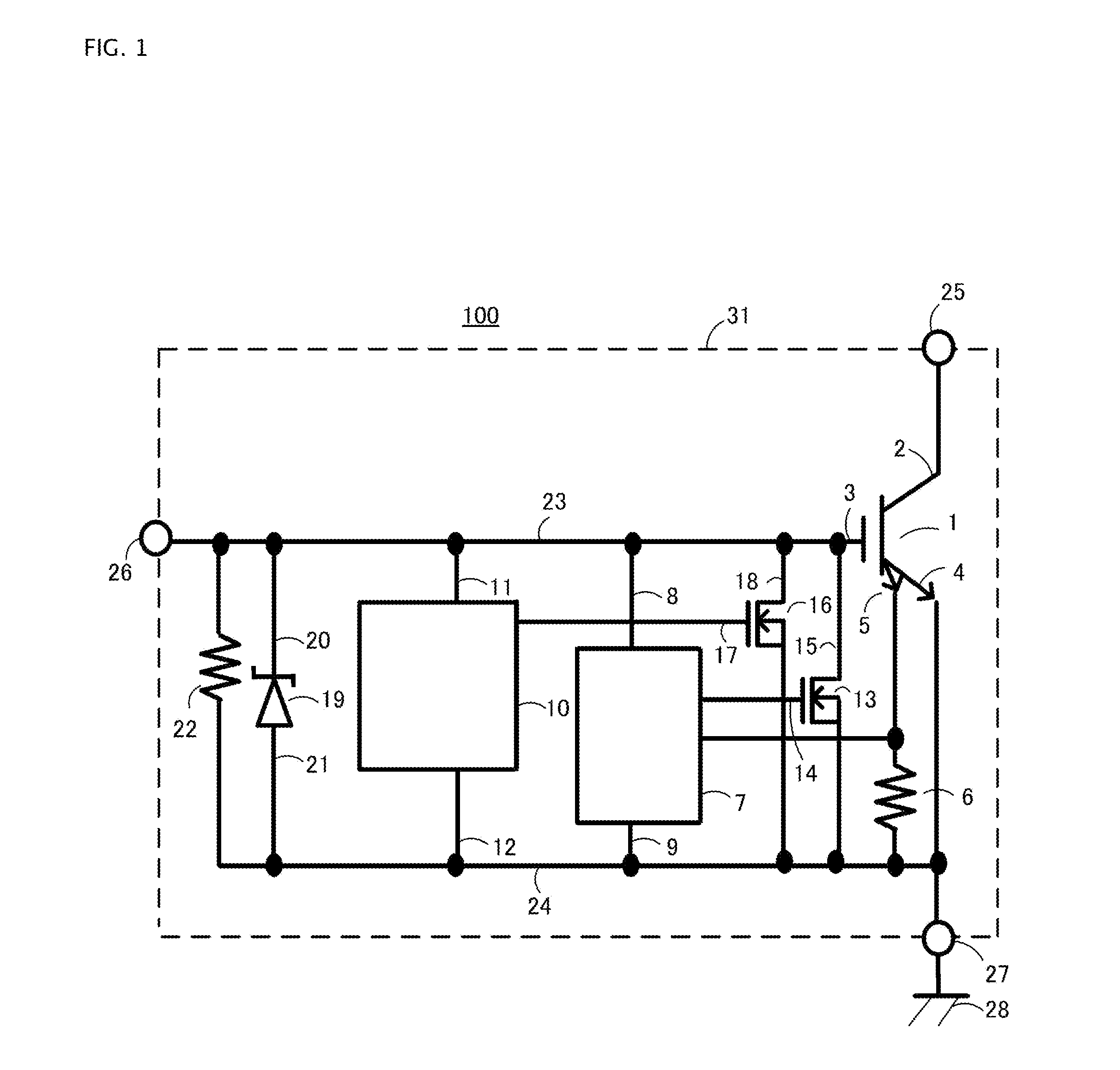
[0085]FIG. 1 is a configuration diagram of a single chip igniter 100 used in an internal combustion engine ignition device according to a first embodiment of the invention, wherein FIG. 1 is an overall circuit configuration diagram, while FIG. 2A is a main portion sectional view of an IGBT 1 formed on a semiconductor substrate 31. FIG. 2A shows a main portion sectional view of one cell. Also, although the gate structure of the IGBT 1 is shown here as a planar type, it may also be an unshown trench type. Also, although the IGBT 1 is given as an example of a power device in FIG. 1, it may also be a power MOSFET. As a power MOSFET, it is good to use one in which a sense source corresponding to a sense emitter 4 is formed.

[0086]In FIG. 1, the single chip igniter 100 is configured of the IGBT 1 having a sense emitter 5, a sense resistor 6, a current limiter circuit 7, an overheat detector circuit 10, a surge protection Zener diode 19 and resistor 22, a first MOSFET 13, a second MOSFE...

embodiment 2

Circuit

[0117]FIG. 5 is a main portion configuration diagram of the single chip igniter 100 used in an internal combustion engine ignition device according to a second embodiment of the invention. The diagram is a main portion circuit diagram of the current limiter circuit 7 configuring the single chip igniter 100.

[0118]To reduce the operating voltages of the current limiter circuit 7 and the unshown overheat detector circuit 10, it is necessary to reduce the gate thresholds of MOSFETs (n-type MOS) configuring the circuits 7 and 10. A measure for doing so is the same as the measure employed for the IGBT 1.

[0119]Also, it is possible to reduce the operating voltage by adjusting the circuit configuration. An example thereof will be described using the current limiter circuit 7.

[0120]A heretofore known current limiter circuit 57 shown in FIG. 9 is formed using an operational amplifier configured of an n-type MOS circuit of a serial three-stage configuration, as shown in FIG. 6A. Specific...

embodiment 3

Noise Countermeasure and Surge Protection

[0126]FIG. 7 is a main portion configuration diagram of the single chip igniter 100 used in an internal combustion engine ignition device according to a third embodiment of the invention.

[0127]In FIG. 7, a capacitor 42 is connected between the gate wiring 23 and ground wiring 24. Installing the capacitor 42 has the result that, even when noise of negative polarity is superimposed in a condition in which the gate voltage input into the gate terminal 26 is reduced to 1.5V, which is the minimum operating voltage, a drop in the gate voltage is prevented by the capacitor voltage. As a result of this, it is possible to cause the current limiter circuit 7, overheat detector circuit 10, and IGBT 1 to operate stably. That is, by installing the capacitor 42, it is possible to increase the noise tolerance of the single chip igniter 100.

[0128]Also, there is the same advantage when providing capacitors 43 and 44 in the current limiter circuit 7 and overhe...


PUM


Abstract

Aspects of the invention are directed to a single chip igniter such that it is possible to realize a reduction in operating voltage, an increase in noise tolerance, a reduction in size, and a reduction in cost. By reducing the gate threshold voltage of a MOS transistor, and reducing the operating voltages of a current limiter circuit, an overheat detector circuit, a timer circuit, an overvoltage protection circuit, an input hysteresis circuit, and the like, it is possible to reduce the operating voltage of a single chip igniter. In some aspects of the invention, the effective gate voltage of the MOS transistor is 1V or more, and the channel length of the MOS transistor is 4 μm or less. Also, in some aspects of the invention, the thickness of a gate oxide film of the MOS transistor is 5 nm or more, 25 nm or less.

Description

BACKGROUND OF THE INVENTION[0001]1. Field of the Invention[0002]Embodiments of the invention relate to low voltage drive single chip igniters, and to internal combustion engine ignition devices that include single chip igniters.[0003]2. Description of Related Art[0004]FIG. 8 is a main portion configuration diagram of an internal combustion engine ignition device 500 in which is mounted a heretofore known single chip igniter 501.[0005]The internal combustion engine ignition device 500 is configured mainly of the single chip igniter 501, an ignition coil 502, a spark plug 503, a battery 504, and an engine control unit (ECU) 505. Of the reference signs in the diagram, 75, 76, and 77 are a collector terminal, a gate terminal, and an emitter terminal of the single chip igniter 501. Also, 51 is an IGBT including a sense IGBT, and 56 is a sense resistor.[0006]FIG. 9 is a main portion circuit diagram of the heretofore known single chip igniter 501 mounted in the internal combustion engine i...

Claims


Application Information

Patent Timeline
Patent Type & Authority Patents(United States)
IPC IPC(8): F02P11/00F02P3/05F02P3/055H01L27/06
CPCF02P11/00F02P3/05F02P3/055H01L27/0635H01L2924/181H01L2224/48247H01L27/0629H01L2924/13055H01L2924/13091H01L2924/00012H01L2924/00
Inventor ISHII, KENICHI
Owner FUJI ELECTRIC CO LTD
Why Eureka
Try Eureka