Use of a process for hydrogen production

a technology of hydrogen production and process, applied in the direction of gas-gas reaction process, physical/chemical process catalyst, bulk chemical production, etc., can solve the problems of low hydrogen technology, and low hydrogen production efficiency, and achieve the production of hydrogen from fossil energy carriers absolutely clean and efficien

Active Publication Date: 2017-02-07
BESTRONG INT
View PDF45 Cites 5 Cited by
  • Summary
  • Abstract
  • Description
  • Claims
  • Application Information

AI Technical Summary

Benefits of technology

[0119]In accordance with the invention, these problems can be addressed and eliminated by the filling station or application according to the invention. Preferably, the filling station, and the use for the production at a filling station using the reactor device as herein, are already generally described above.

Problems solved by technology

Since energy losses occur at every energy conversion, the hydrogen supply infrastructure is, at present, relatively inefficient due to its complexity.
This constitutes an essential disadvantage, in particular, in the spreading of hydrogen technologies for use as fuels, either in fuel cells or in internal combustion engines, as a substitution for non-renewable fossil fuels.
It may also be anticipated that underground storage of collected CO2, to the extent coupled with conventional steam reforming processes, will not rapidly lead to absolutely clean production of hydrogen from fossil energy carriers.
With reference to the Kyoto Protocol and various national legislatures aimed at minimizing greenhouse gases, the greatest drawback of the SMR process is its high CO2 emission.
On the other hand, it is a very energy-intensive process.
There, it turned out those transition metals exhibited high activities in terms of methane decomposition, yet with the drawback of carbon layers depositing on the surfaces of the catalysts.
Yet, hydrogen can also be stored in liquid form at minus 253° C. All these types of storage involve considerable energy expenditures, both in terms of storage and in terms of maintaining, e.g., a cooled storage tank.
If hydrogen is stored in high-pressure gas bottles of steel, only very little gas can be transported at a considerable weight.
Thus, a 40-ton truck will only be able to transport about 530 kilograms of gaseous hydrogen in steel bottles.
As in the case of storage, considerable energy losses will have to be taken into account during transportation.
Due to the high energy consumption in the form of electric power during the electrolysis of water, this method is, however, neither economical nor ecological, considering that current is primarily obtained by the combustion of fossil fuels.
Another problem involved in the use of hydrogen as a fuel for motor vehicles is its low energy density as compared to gasoline or diesel.
Fuel consumption will consequently be higher, and vehicles will have to be equipped with larger tanks.
The establishment of a hydrogen-oriented infrastructure is an expensive project.
At present, hydrogen is not able to compete on the market with conventional hydrocarbon-based fuels.

Method used


Image

  • Use of a process for hydrogen production
  • Use of a process for hydrogen production
  • Use of a process for hydrogen production

Examples


example 1

[0129]Ni(OH)2 was prepared from an aqueous nickel nitrate solution by ammonia precipitation at pH 9. The precipitate was collected in a Buchner funnel, thoroughly washed with deionized water, followed by acetone, and dried at 100° C. for several hours. 4.5 g of the thus prepared Ni(OH)2 powder were suspended in 100 ml acetone under vigorous stirring and then supplemented with 2 ml TEOS (tetraethoxysilane), 5 ml water and 2 ml ammonium hydroxide (25%). The suspension was mechanically stirred overnight so as to ensure that virtually all of the TEOS was homogenously applied as SiO2 on the Ni(OH)2 precipitate. The solid residue was filtered, washed as above, and dried at 120° C. for several hours.

example 2

[0130]200 mg of the composite catalyst were loaded into a ceramic boat, which was inserted into a tubular furnace including a hot zone of 30 cm and equipped with a quartz tube of 40 mm diameter and 1000 mm length. The quartz tube was closed on both ends by suitable closures comprising gas supply and gas outlet means.

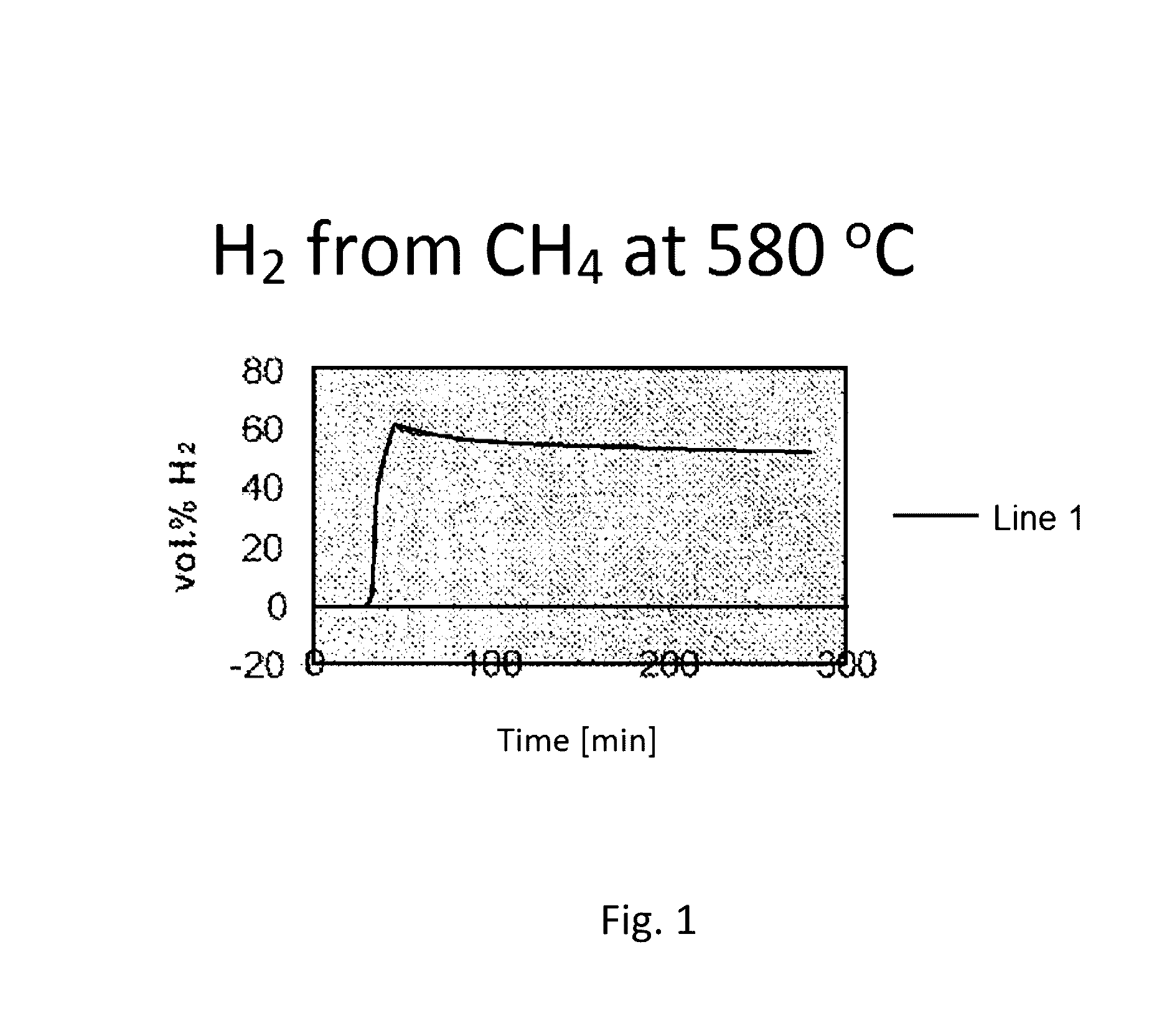
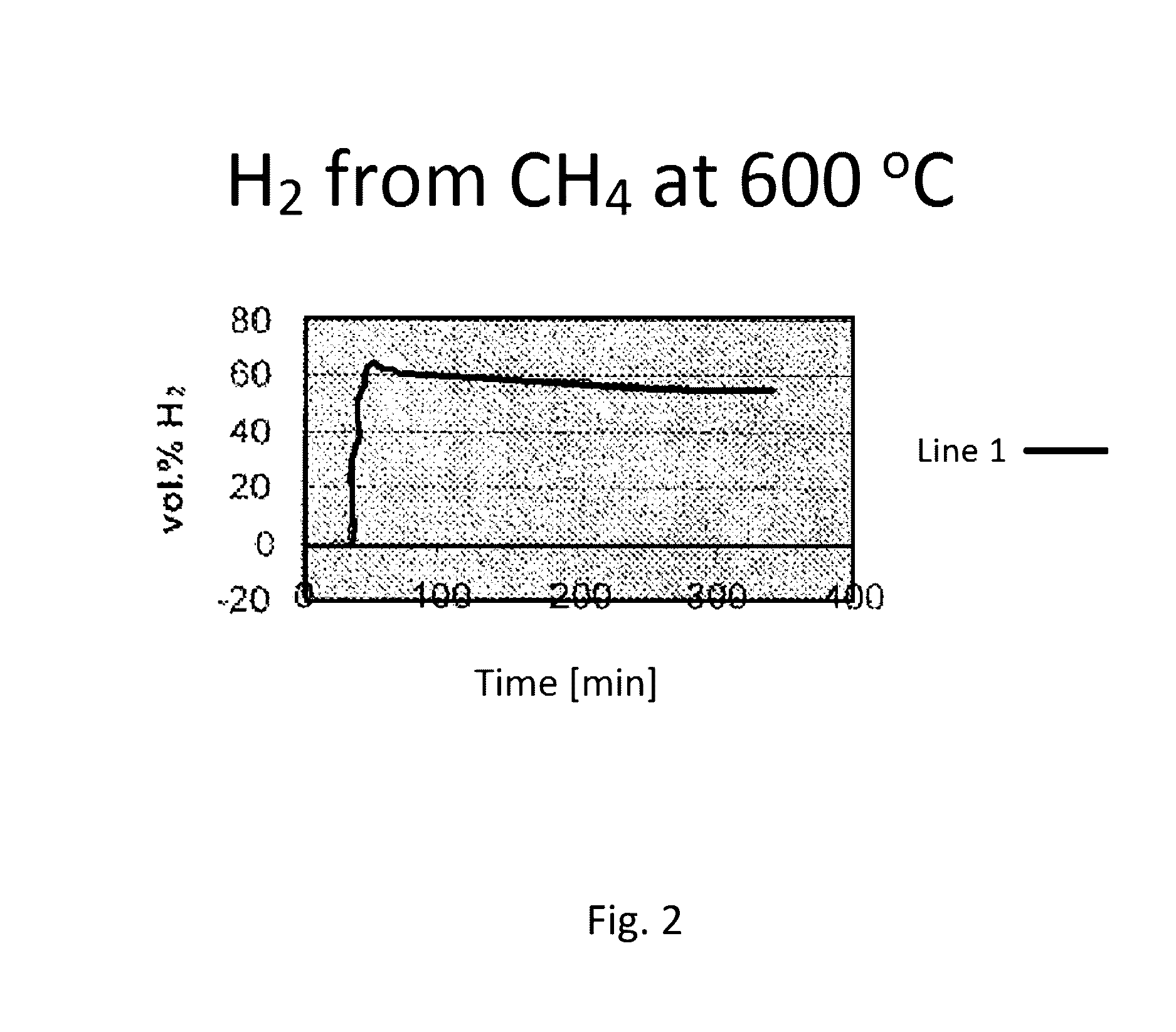
[0131]The whole system was flushed with pure methane. After having started heating to the CVD reaction temperature of 620° C., a methane gas flow of 90 ml / min was adjusted. The heating rate was 10° C. per minute, and a constant temperature of 620° C. was maintained for 4 hours. When reaching a temperature of 350° C., an increase in the hydrogen content was observed in the exhaust gas. After 20 minutes, and having reached of the reaction temperature, a hydrogen concentration of 68 vol % was measured in the exhaust gas. During the four-hour test period, the hydrogen concentration dropped continuously, still amounting to 51 vol % at the end. After cooling to room temperatur...

example 3

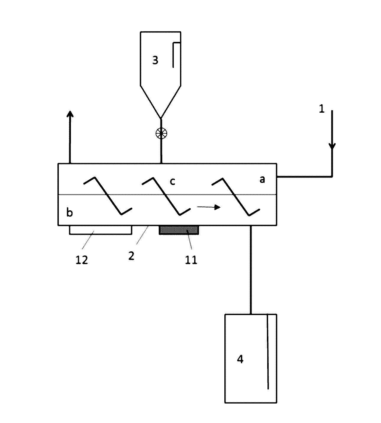
[0133]A filling station facility according to the present invention will now be explained in more detail with reference to FIG. 4. This schematic illustration depicts an inlet for a hydrocarbon-containing feed gas (a) into a reformer (c). In the reformer, the feed gas is reacted to hydrogen on a catalyst under reaction conditions. In the present embodiment, the reformer (c) comprises a supply and discharge device (cl) for the continuous supply and discharge of the catalyst. The hydrogen-containing exhaust gas of the reformer is facultatively conducted, via an exhaust gas line (j) that is suitable for the transport of hydrogen, i.e. sufficiently tight, both directly and through a steam reformer (d), via a mixing device (k), into a compressor or a cooling device (f). The feed gas injected into the reformer is preferably preheated via a heat exchanger (b1) by the exhaust gas (j) from the reformer, or from the steam reformer. The steam reformer is equipped with a steam inlet (e). The st...


PUM

PropertyMeasurementUnit
temperaturesaaaaaaaaaa
operating temperaturesaaaaaaaaaa

Abstract

The present invention relates to the use of a process for hydrogen production in which at least a part of a hydrocarbonaceous feed gas (a) is passed into a reformer (c), wherein the feed gas is contacted in the reformer with a catalyst and the feed gas is converted to hydrogen and solid carbon, for the direct production of a hydrogenous gas at filling stations for sale to a consumer, and also to a reactor (d) for hydrogen production.

Description

CROSS REFERENCE TO RELATED APPLICATIONS[0001]This application is divided from U.S. patent application Ser. No. 12 / 092,231 derived from International Application No. PCT / AT06 / 00441 filed on Oct. 27, 2006, content of which is incorporated herein in its entirety.FIELD OF THE INVENTION[0002]The present invention relates to the field of hydrogen production and its distribution infrastructure.BACKGROUND OF THE INVENTION[0003]There has been great interest in hydrogen as an energy carrier in the transport sector. Hydrogen is perceived as environmentally friendly, in particular, because no CO2 emissions are caused at its combustion by the end consumer. This view, however, ignores that greenhouse gas emissions are caused during its production and supply. Since energy losses occur at every energy conversion, the hydrogen supply infrastructure is, at present, relatively inefficient due to its complexity. This constitutes an essential disadvantage, in particular, in the spreading of hydrogen tec...

Claims


Application Information

Patent Timeline
Patent Type & Authority Patents(United States)
IPC IPC(8): C01B3/26B01J23/882C01B3/28B82Y40/00B82Y30/00C01B3/38B01J23/755B01J12/00B01J37/03
CPCC01B3/26B01J12/005B01J23/755B01J23/882B01J37/033B01J37/035B82Y30/00B82Y40/00C01B3/28C01B3/382C01B31/0226C01B31/0293B01J2523/00C01B2203/0233C01B2203/0277C01B2203/043C01B2203/044C01B2203/047C01B2203/085C01B2203/0833C01B2203/1047C01B2203/1052C01B2203/1082C01B2203/1241C01B2203/142Y02P20/129B01J2523/22B01J2523/68B01J2523/845C01B32/16C01B32/18Y02P20/52
Inventor HAMMEL, ERNSTMAUTHNER, KLAUS-DIETERBRICHTA, WALTER
Owner BESTRONG INT
Why Eureka
Try Eureka