Method of preparing metal roller with surface relief microstructure

A technology of a metal roller and a manufacturing method, which is applied in the direction of producing a decorative surface effect, microlithography exposure equipment, and photolithography exposure equipment, etc., and can solve the problems of affecting service life, easy formation of crater effect, and low absorption rate and other issues to achieve the effect of prolonging the service life

Active Publication Date: 2010-12-15
苏州迈塔光电科技有限公司 +2
View PDF3 Cites 2 Cited by
  • Summary
  • Abstract
  • Description
  • Claims
  • Application Information

AI Technical Summary

Problems solved by technology

The above method has the following disadvantages: (1) the hardness of the nickel plate is low, and it is easily damaged in the molding production, which affects the service life; (2) due to the production of the flat work nickel plate, and then wrapping it on the cylinder, a splicing seam will be produced. In continuous rolling molding, there will be a seam every other perimeter, and there will be a large number of seams on the produced product, so it is not suitable for continuous high-speed rotary printing
The existing problems are: (1) When pulsed lasers with wavelengths of 1060nm and 532nm process the surface of materials (such as metals), the material has a low absorption rate of light and the thermal effect is very obvious. During processing, the material is ablated by locally generating high temperature , a large amount of light energy is converted into heat energy, forming a crater effect; (2) In order to obtain a high average power laser output, the laser beam used is a multi-transverse mode spot, and the spot quality is poor (M 2 <10), therefore, the minimum light spot is generally around 30-50 μm, the multi-mode laser beam cannot be focused into a thinner beam, and the processing accuracy is limited; (3) In order to obtain a deeper processing effect, high repetition frequency pulse work ( ~20kHz) mode, using vectorization mode during scanning, forming multiple repeated laser pulse processing at the same processing position (light spot), the material has a low absorption rate of the first pulse laser, but the energy absorption of subsequent pulses increases , which is conducive to deeper processing, but is more prone to cratering
[0019] However, when the above-mentioned process is directly transplanted to the surface of the metal drum to process the microstructure, it encounters difficulties
The main problem is that, unlike silicon substrates, the etch rate of metal is much lower than that of photoresist, so that the photoresist needs to be etched deeply, when the duty cycle of the photoresist grating groove ( When depth / stripe width) is greater than 2:1, the etching of photoresist is more difficult; A New Process Method for Fabricating Microstructures on Rollers

Method used


Image

  • Method of preparing metal roller with surface relief microstructure
  • Method of preparing metal roller with surface relief microstructure
  • Method of preparing metal roller with surface relief microstructure

Examples


Embodiment 1

[0047] Embodiment one: see attached Figure 4 Shown, a kind of manufacture method with surface relief microstructure metal cylinder comprises the following steps:

[0048] [1] First make a polished metal roller;

[0049] [2] Coating photoresist;

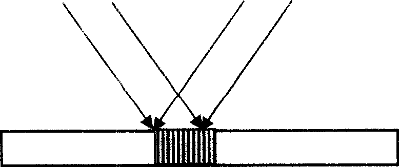
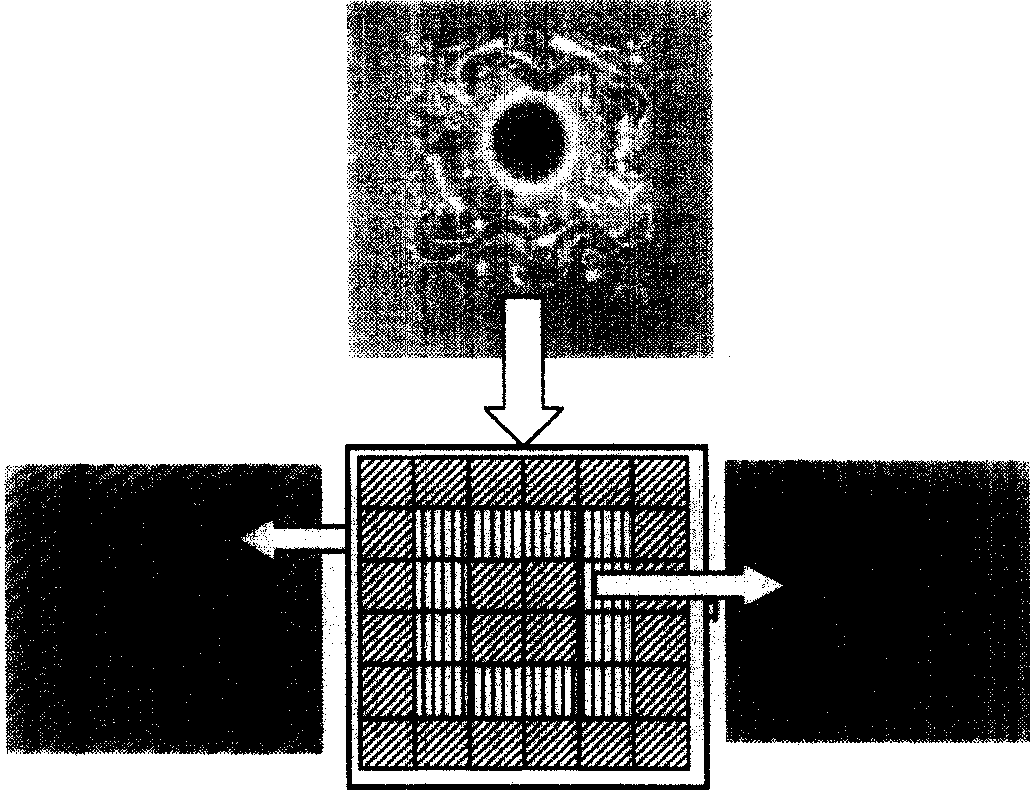
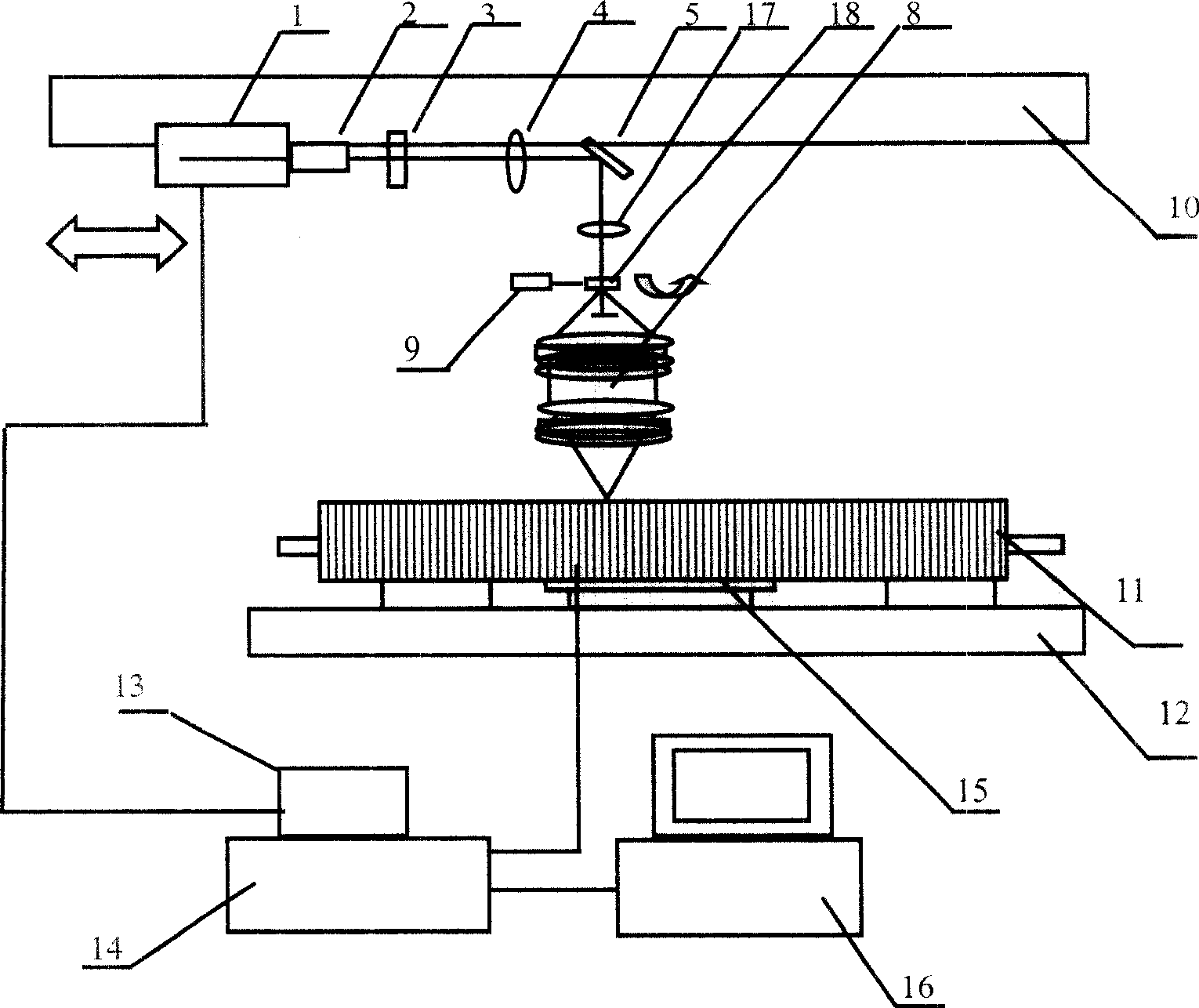
[0050] [3] Interferometric lithography was performed on a photoresist roll, using an attached image 3 The lithography method of the interference lithography device shown is: convert the image distribution into a pulse control signal, according to the orientation and space frequency of the unit grating, simultaneously carry out the interference optical head, platform movement, high-speed rotation of the grating and optical pulse input, step by step Continuous exposure on the drum-type photoresist is detoured, and the drum, optical head, and beam splitting element do not need to pause during exposure until the entire image is produced.

[0051] The laser lithography direct writing system realizing the above method includes a DPSSL ...

Embodiment 2

[0057] Embodiment two: see attached Figure 4 as shown,

[0058] [1] First make a polished metal roller;

[0059] [2] Coating photoresist;

[0060] [3] Perform interference lithography on a photoresist roller;

[0061] [4] Put the roller after photolithography into the developer to ensure that the bottom of the grating groove is exposed (up to the metal surface), and clean it;

[0062] [5] Activate the metal roller, place it in the electroforming solution, connect the metal roller to the cathode, and place the nickel metal material on the anode. After electrification, the anode nickel is ionized to form cations and deposit to the cathode. This forms a metal nickel-plated cylinder.

[0063] [6] After the deposition is completed, it is cleaned, and then the rotating drum is sprayed with an alkaline solution or a photoresist solvent to completely remove the photoresist.

[0064] [7] After cleaning, the microstructure processing of the metal drum is completed.


PUM

PropertyMeasurementUnit
surface smoothnessaaaaaaaaaa
thicknessaaaaaaaaaa

Abstract

The invention discloses a preparing method of metallic roller with surface relief microstructure, which comprises the following steps: (1) applying photo resist on the metallic roller; producing microstructure mask on the photo resist; removing light part until metallic surface emergence through development; (2) placing the processing metallic roller in electromoulding solution; connecting to electrical source negative pole; proceeding metallic electrodeposition with the thickness of deposition at 150-500 nanometer; (3) getting out of metallic roller from electromoulding solution; removing surplus photo resist; getting the metallic roller. This invention combines the photolithographic process and electromoulding to realize the production of metallic roller.

Description

technical field [0001] The invention relates to the field of micro-machining metal surfaces, in particular to a method for machining relief microstructures on the surface of a cylinder by combining methods such as laser interference lithography and electroforming. Background technique [0002] In order to replicate surface relief microstructures in large quantities, the LIGA (lithography-electroforming) process is usually used to facilitate the replication of the mother board. On the cathode of the electroforming tank, a metal nickel plate of a certain thickness is deposited on the photoresist, and then separated from the photoresist. A relief structure is formed on the metal nickel plate, and a metal nickel master plate is made. Then use the master plate to recast the metal working plate. Here, the advantage of the photolithography-electroforming process is that the electroforming copy is fast and easy. [0003] In the actual replication production process, it is necessary...

Claims


Application Information

Patent Timeline
Patent Type & Authority Patents(China)
IPC IPC(8): C25D1/00C25D5/02B44C1/04G03F7/20
Inventor 魏国军陈林森周小红浦东林解正东
Owner 苏州迈塔光电科技有限公司
Why Eureka
Try Eureka