Multifunctional light-absorbing, scattering and transmitting spectrograph based on surface plasma wave
A technology of surface plasmon waves and spectrometers, which is applied in the direction of scattering characteristic measurement, color/spectral characteristic measurement, instruments, etc., can solve the problems of inability to realize multi-spectrum correlation, low scalability, and not involving Rayleigh scattering spectrum detection, etc.
- Summary
- Abstract
- Description
- Claims
- Application Information
AI Technical Summary
Problems solved by technology
Method used
Image
Examples
Embodiment 1
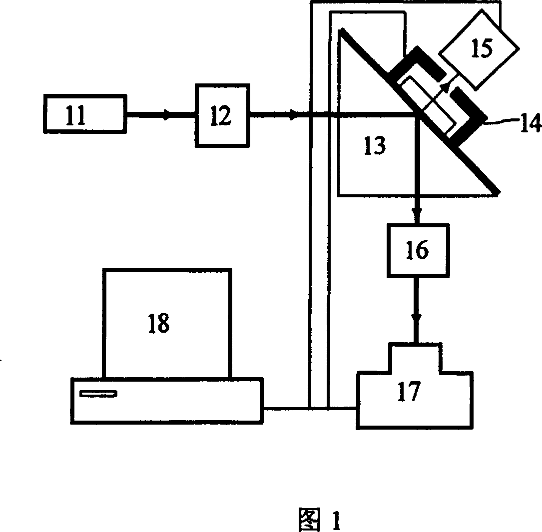
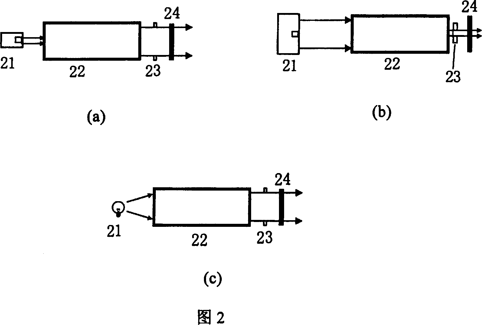
[0058] The basic structure of the multifunctional light absorption, scattering and emission spectrometer based on surface plasmon waves of the present invention is shown in FIG. 1 . Among them, 11 is the light source, selected according to the needs of the test, which can be semiconductor laser, He-Ne laser, dye laser, halogen tungsten lamp, xenon lamp, Nernst lamp, silicon carbide rod lamp or continuous wavelength light-emitting diode; 12 is incident light modulation system; 13 is an electromagnetic coupling reaction system, in which the prism is an example of a common isosceles right-angled triangular prism; 14 is a temperature control system; 15 is an emitted light detection system, 16 is a reflected light detection system, and 17 is a data acquisition and management system , 18 are microcomputers.
[0059] Data acquisition and management system: This part is mainly composed of data acquisition card, data processing and analysis software and computer, which can complete tas...
Embodiment 2
[0064] Since scattered light detection is the most difficult to implement among the fluorescence, Raman, scattering, and surface plasmon resonance spectra, an example of the collection of scattered signals is given here emphatically. A 50nm-thick gold film was coated on the bottom of the prism as a sensing film, a He-Ne laser was used as a light source, a photomultiplier tube was used as a scattered light detector, and the iodide-rhodamine B ion association system was used as a probe. Concentration of KIO 3 taking the test. The flow injection analysis results are shown in Figure 7. Determination of KIO 3 The minimum detection limit was 100 nmol / L.
Embodiment 3
[0066] The same light source, detector and resonance light scattering probe as in Example 2 were used. A 50nm-thick gold film is coated on the bottom of the prism as a highly reflective sensing film, and the sensing film is chemically modified to inhibit the non-specific adsorption of samples on the surface of the sensing film. Under these conditions, the concentration analysis of Cr(VI) was carried out. The optimized angle diagram is shown in Figure 8, and Figure 9 shows the results of flow injection analysis of different concentrations of Cr(VI). The minimum detection limit of Cr(VI) by this method is 40 nmol / L.
PUM
| Property | Measurement | Unit |
|---|---|---|
| Thickness | aaaaa | aaaaa |
Abstract
Description
Claims
Application Information
 - R&D
- Intellectual Property
- Life Sciences
- Materials
- Tech Scout
- Unparalleled Data Quality
- Higher Quality Content
- 60% Fewer Hallucinations
Browse by: Latest US Patents, China's latest patents, Technical Efficacy Thesaurus, Application Domain, Technology Topic, Popular Technical Reports.
© 2025 PatSnap. All rights reserved.Legal|Privacy policy|Modern Slavery Act Transparency Statement|Sitemap|About US| Contact US: help@patsnap.com


