Dielectric adjustable thin film based on implantation type nano line electrode and preparation thereof
A nanowire, implantable technology, applied in chemical instruments and methods, circuits, electrical components, etc., to achieve good application prospects, fewer defects, and less loss.
- Summary
- Abstract
- Description
- Claims
- Application Information
AI Technical Summary
Problems solved by technology
Method used
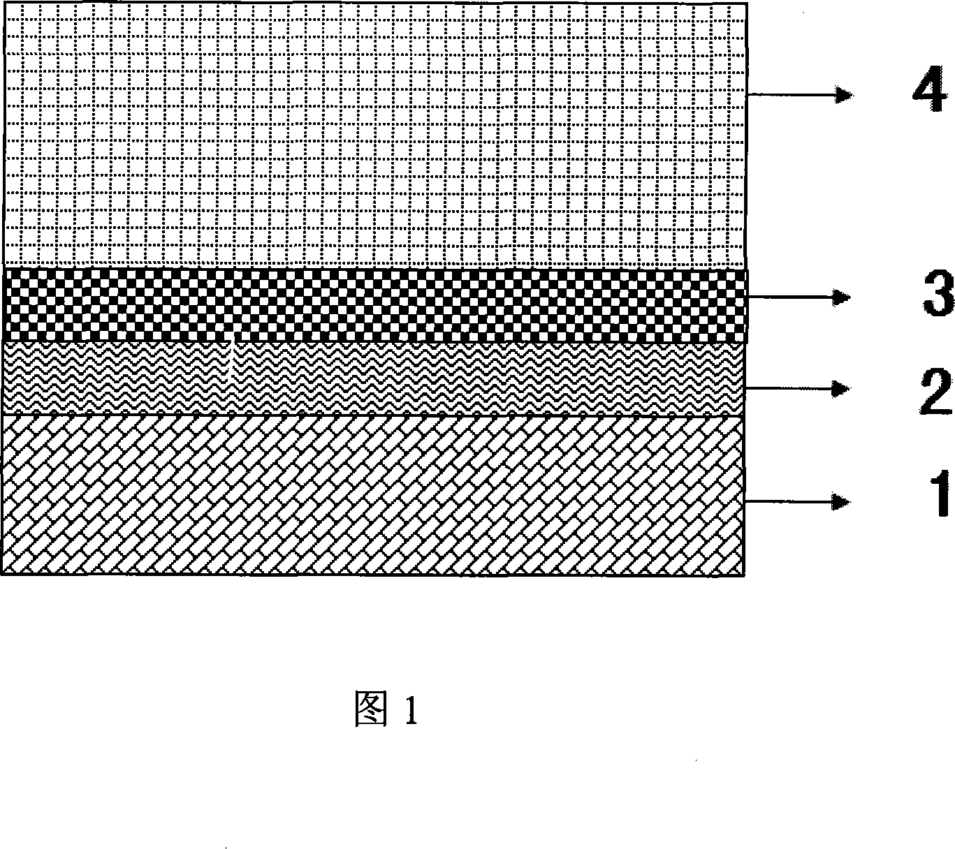
Image

Examples
Embodiment 1
[0034] 1) According to the chemical formula Pb x Sr 1-x TiO 3 , x=0.4, take powdered strontium carbonate, lead oxide and titanium dioxide, in which the lead oxide is over 0.02% mol to compensate for the volatilization loss of lead; mix by ball milling, then press the target, and sinter the target material Pb 0.4 Sr 0.6 TiO 3 ;
[0035] 2) Clean the glass substrate, and sequentially deposit Ti on the substrate by chemical vapor deposition 5 Si 3 Conductive film layer and TiSi conductive nanowire layer;
[0036] 3) Sputtering deposition of a dielectric film Pb on the titanium silicide conductive nanowire layer of the composite structure obtained in step 2) by magnetron sputtering 0.4 Sr 0.6 TiO 3 ; During sputtering, the vacuum degree of the reaction chamber was kept at 0.6Pa, with argon and oxygen as the sputtering atmosphere, the flow rates of argon and oxygen were 10sccm and 10sccm respectively, the sputtering power was 80W, and the sputtering time was 2h;
[0037] ...
Embodiment 2
[0040] 1) According to the chemical formula Pb x Sr 1-x TiO 3 , x = 0.1, take powdered strontium carbonate, lead oxide and titanium dioxide, in which the lead oxide is over 0.02% mol to compensate for the volatilization loss of lead; mix by ball milling, then press the target, and sinter the target material Pb 0.1 Sr 0.9 TiO 3 ;
[0041] 2) Clean the single crystal silicon substrate, and sequentially deposit Ti on the substrate by chemical vapor deposition 5 Si 3 conductive film layer and TiSi 2 conductive nanowire layer;
[0042] 3) Sputtering deposition of a dielectric film Pb on the titanium silicide conductive nanowire layer of the composite structure obtained in step 2) by magnetron sputtering 0.1 Sr 0.9 TiO 3 ; During sputtering, the vacuum degree of the reaction chamber was kept at 0.8Pa, with argon and oxygen as the sputtering atmosphere, the flow rates of argon and oxygen were 3sccm and 27sccm respectively, the sputtering power was 60W, and the sputtering ti...
Embodiment 3
[0046] 1) According to the chemical formula Pb x Sr 1-x TiO 3 , x=0.9, take powdered strontium carbonate, lead oxide and titanium dioxide, in which the lead oxide is over 0.02% mol to compensate for the volatilization loss of lead; mix by ball milling, then press the target, and sinter the target material Pb 0.9 Sr 0.1 TiO 3 ;
[0047] 2) Clean the polysilicon substrate, and deposit Ti sequentially on the substrate by chemical vapor deposition 5 Si 3 Conductive film layer and TiSi conductive nanowire layer;
[0048] 3) Sputtering deposition of a dielectric film Pb on the titanium silicide conductive nanowire layer of the composite structure obtained in step 2) by magnetron sputtering 0.9 Sr 0.1 TiO 3 ; During sputtering, the vacuum degree of the reaction chamber was kept at 1Pa, with argon and oxygen as the sputtering atmosphere, the flow rates of argon and oxygen were 12sccm and 45sccm respectively, the sputtering power was 90W, and the sputtering time was 2h;
[00...
PUM
 Abstract
Description
Claims
Application Information