Method for forming refractory metal parts by using laser

A refractory metal and laser forming technology, which is applied in the field of metal parts forming and processing, can solve the problems affecting the dimensional accuracy of parts, difficult to directly form parts, and inability to directly form, so as to avoid dimensional deviation, avoid machining and save materials Effect

Inactive Publication Date: 2010-07-21
HEILONGJIANG UNIVERSITY OF SCIENCE AND TECHNOLOGY
View PDF0 Cites 66 Cited by
  • Summary
  • Abstract
  • Description
  • Claims
  • Application Information

AI Technical Summary

Problems solved by technology
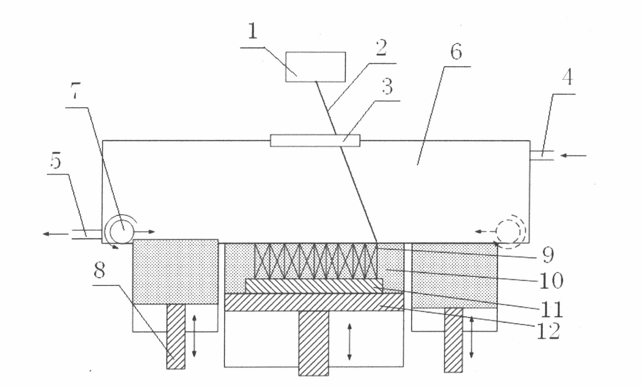
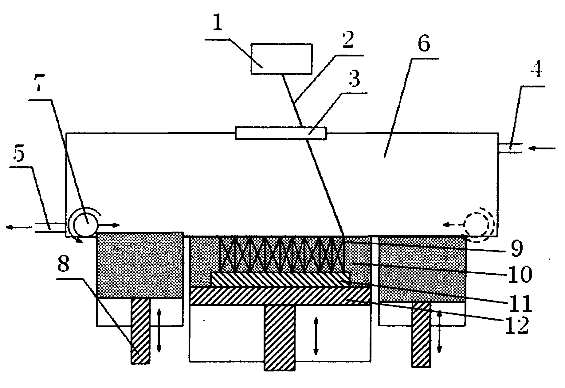
[0004] (1) Powder metallurgy liquid phase sintering method is difficult to directly form parts with arbitrary complex shapes
In the application of refractory materials, if a certain complex shape is required, the powder metallurgy liquid phase sintering method cannot be directly formed due to the limitation of the process
In actual production, mechanical processing and follow-up processing are often required. This method is not only cumbersome,

Method used


Image

  • Method for forming refractory metal parts by using laser
  • Method for forming refractory metal parts by using laser
  • Method for forming refractory metal parts by using laser

Examples


Embodiment 1

[0030] (1) The computer uses 3D modeling software (such as UG, Pro / E, etc.) to design the CAD 3D model of the part, and then it is processed by the slicing software and saved as an STL file, and the data information of the STL file is input to the SLM rapid prototyping system.

[0031] (2) In the SLM rapid prototyping system, a layer of W-Ni mixed powder with a thickness of about 0.1-0.2 mm is spread on the metal substrate by the powder feeding mechanism (wherein the mass fraction of W is ≥ 80%, and the particle size is about 10 ~100μm).

[0032] (3) Use a YAG laser or a fiber laser with a laser power of 200W to scan the slice after selecting the scanning path to melt the refractory mixed metal powder, wherein the scanning speed is 100-300mm / s.

[0033] (4), repeat the above steps (2)-(3), until the shell processing of the whole part is completed, at this time, the SLM processing of the W-Ni refractory metal complex metal part is completed.

[0034] Finally, follow-up process...

example 2

[0036] (1) Use 3D modeling software (such as UG, Pro / E, etc.) to design the CAD 3D model of the refractory part, then process it with the slicing software and save it as an STL file, and input the data information of the STL file into the SLM rapid prototyping system .

[0037] (2) Spread a layer of tungsten powder with a thickness of about 0.05~0.15mm (particle size about 10~100μm) on the metal substrate by the powder feeding mechanism.

[0038](3) Use a YAG laser with a laser power of 200W to scan the slice after selecting the processing path to melt the tungsten powder, wherein the scanning speed is 50-100 mm / s.

[0039] (4) Steps (2)-(3) are repeated until the tungsten metal part with a certain complex shape is processed.

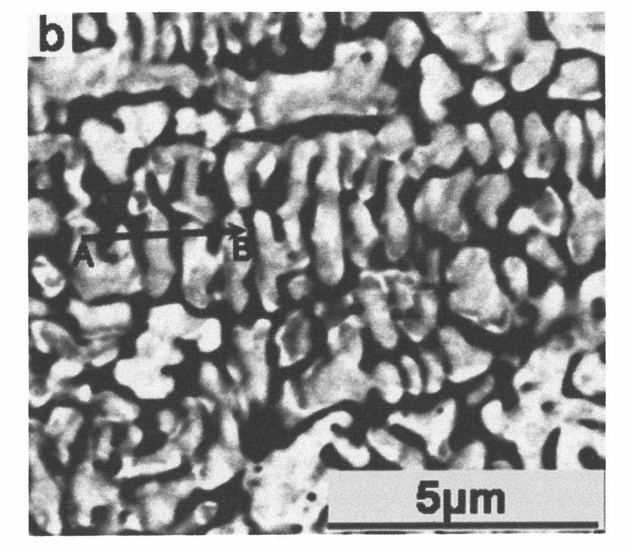
[0040] like figure 2 Shown is the metallographic diagram after the 200W YAG laser is used to scan and select the processing path to melt the tungsten powder.

[0041] After processing the obtained tungsten metal parts with complex shapes through mec...

example 3

[0043] (1) Use 3D modeling software (such as UG, Pro / E, etc.) to design the CAD 3D model of the refractory part, then process it with the slicing software and save it as an STL file, and input the data information of the STL file into the SLM rapid prototyping system .

[0044] (2) Spread a layer of Mo-Si mixed powder (with a particle size of about 10-100 μm) with a thickness of about 0.02-0.15 mm on the metal substrate by a powder feeding mechanism.

[0045] (3) A fiber laser with a laser power of 200W is used to scan the slice after the selected processing path to melt the Mo-Si mixed powder, wherein the scanning speed is 50-100 mm / s.

[0046] (4) Steps (2)-(3) are repeated until the molybdenum metal parts with a certain complex shape are processed.

[0047] After processing the obtained tungsten metal parts with complex shapes through mechanical polishing and other steps, MoSi with certain complex shapes and sizes can be obtained. 2 Refractory metal parts.

[0048] In th...


PUM

PropertyMeasurementUnit
Particle sizeaaaaaaaaaa

Abstract

The invention provides a method for preparing parts with high-melting point metal powder and the method combines selective laser fusion rapid prototyping technology with powder sintering and forming technology. The method comprises the following steps: firstly, a three-dimensional modeling software is used to design the CAD models of parts, secondly, a slice processing software is used to generate multilayer slice information to be stored as STL files, the data of the STL files are transmitted to a selective laser melting rapid forming system; then in the selective laser melting rapid forming system, a layer of powder to be processed with the thickness of 0.05-0.2mm is laid on a platform by a powder-sending mechanism, a YAG laser or optical fiber laser with the laser power of more than 200W is used to scan the powder to be processed in a scanning speed of 20-300mm/s; and finally the powder is molten to accumulate the parts. The method does not need moulds and is characterized in that the technology has high controllability, does not adopt post-processing, is simple and practical and can be used to prepare parts with complicated shapes.

Description

technical field [0001] The invention relates to the field of forming and processing of metal parts, in particular to a method for manufacturing parts by using metal powders with high melting points such as tungsten and molybdenum which are difficult to melt. The method utilizes metal powder selective laser melting technology to process refractory metals into parts. Background technique [0002] Refractory material is a pure metal or alloy material composed of tungsten, molybdenum and other refractory metals or some other elements. Compared with traditional alloy materials, the typical characteristics of refractory materials are high melting point, usually around 3000°C, so it is difficult to cast and smelt, and powder metallurgy is often used for processing. In recent years, refractory material parts have been widely used due to their excellent properties; taking tungsten-based alloys as an example, they have the following excellent properties, such as high density, good ten...

Claims


Application Information

Patent Timeline
IPC IPC(8): B22F3/105B23K26/00C23C24/10B23K26/34
CPCY02P10/25
Inventor 刘锦辉赵灿李瑞迪张丹青陈继兵
Owner HEILONGJIANG UNIVERSITY OF SCIENCE AND TECHNOLOGY
Why Eureka
Try Eureka