Municipal sludge energy treatment system

A technology for treating system and municipal sludge, applied in biological sludge treatment, waste fuel, etc., can solve problems such as failure of normal operation or outage of key equipment, failure to maintain a stable high organic load, and reduction of system processing efficiency, etc. Small land area, high organic load and organic matter removal rate, and the effect of improving treatment efficiency

Active Publication Date: 2010-12-08
广州微启生物科技有限公司
View PDF6 Cites 8 Cited by
  • Summary
  • Abstract
  • Description
  • Claims
  • Application Information

AI Technical Summary

Problems solved by technology

However, in actual operation, acid-producing bacteria often enter the methanogenic reactor with the effluent, which not only causes the loss of acid-producing bacteria, cannot fully hydrolyze and acidify macromolecular organic matter, but also causes harm to the growth of methanogenic bacteria in the methanogenic reactor. Affect gas production fermentation and reduce the processing efficiency of the whole system
[0006] In addition, in many sewage treatment plant sludge anaerobic digestion systems that have been in operation in my country, the biogas production fluctuates greatly, resulting in large fluctuations in power generation, and key equipment such as biogas power generation cannot operate normally or shut down, etc.
This low yield phenomenon is mainly caused by the inability to maintain a stable high organic load during anaerobic digestion

Method used


Image

  • Municipal sludge energy treatment system
  • Municipal sludge energy treatment system

Examples


Embodiment 1

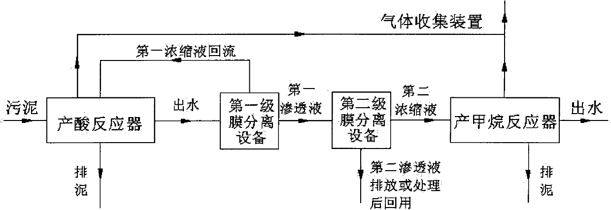
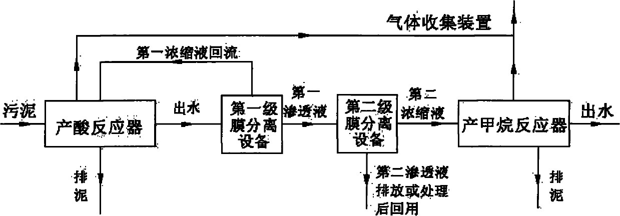
[0024] Equipment: Pilot scale, the diameter of the acid production reaction pool is 2.5m, the height is 2.1m, and the effective volume is about 10m 3 , the bottom inclination angle can be 20°; the methanogenic reaction pool adopts a rectangular shape, the length, width and height are 4m, 3m and 3m respectively, and the effective volume is 30m 3 . One end of the acid production reaction tank is connected to the sludge inlet, and the other end is the water outlet. The water outlet is connected to the first-stage membrane separation equipment (microfiltration vibrating membrane). The connecting pipe enters the second-stage membrane separation equipment (ultrafiltration vibrating membrane), the retentate end of the second-stage membrane separation equipment connects the pipe into the methane production reaction tank, and the permeation end connects the pipe to directly discharge water.

[0025] Both the acid production reaction tank and the methane production reaction tank are pr...

Embodiment 2

[0029] The equipment is as in Example Requirement 1, but the second-stage membrane separation equipment adopts nanofiltration membrane.

[0030]The source of sludge is the same as in Example 1. The sludge enters from one end of the acid production reaction tank, the HRT is set to 2.5 days, the temperature in the tank is 36°C, and then it is output from the other end and enters the first-stage membrane separation equipment, where the separation becomes the first The concentrated liquid and the first permeate at the permeate end, the first concentrated liquid is connected through pipelines and flows back into the acid-generating reaction tank to mix with the newly entered sludge to continue the hydrolysis reaction, prevent the loss of acid-generating bacteria, and maintain a high concentration in the acid-generating reactor. The hydrolyzed acid-producing bacteria; the first permeate enters the second-stage membrane separation equipment and is separated into the second concentrate...

Embodiment 3

[0033] The equipment is as required in Example 1, but the two-stage membrane separation equipment adopts tubular membrane, the first-stage membrane separation adopts ultrafiltration membrane, and the second-stage membrane separation adopts nanofiltration membrane. Under this device, the second permeate can be reused directly, the COD in the methanogenic phase can be maintained at 28000mg / L, the average organic matter decomposition rate of the system can be maintained at about 55%, and the biogas conversion rate of organic matter can be maintained at about 1.1L / g VS , the gas production rate is maintained at 14m 3 / m 3 For wet sludge, the volatile fatty acids in the effluent of the methanogenic phase are lower than 200mg / L. Compared with the vibrating membrane, the tubular membrane is less expensive, but the number of backwashing is more frequent than that of the vibrating membrane.


PUM


Abstract

The invention belongs to the field of sludge treatment and relates to a municipal sludge energy treatment system. The system comprises an acidogenic reactor and a methanogenic reactor; and first-level membrane separation equipment and second-level membrane separation equipment are arranged between the acidogenic reactor and a methanogenic reactor. The sludge passes through the acidogenic reactor and is hydrolyzed to generate acid in the methanogenic reactor, and then passes through the first-level membrane separation equipment to be separated into first concentrated solution and first penetrating fluid. The first concentrated solution reflows to the acidogenic reactor, and the first penetrating fluid enters the second-level membrane separation equipment to be separated into second concentrated solution and second penetrating fluid; and the second concentrated solution enters the methanogenic reactor to be fermented to generate methane. By organically combining the two-phase anaerobic digestion technology with the membrane separation technology, the municipal sludge energy treatment system realizes the combination of a physical dialysis method and a kinetic control method and really realizes the separation of fermentative bacteria bacteria and methanogenic bacteria. Therefore, the bacteria in two phases can exert the maximum activity, and the operating stability and energy efficiency of the whole system are improved.

Description

technical field [0001] The invention belongs to the field of sludge treatment and relates to a municipal sludge treatment system. Background technique [0002] Since the end of the 1990s, my country's urban sewage treatment business has developed rapidly. Urban sewage treatment plants have grown from more than 400 to 792 in 2005, with an annual sludge output of nearly 600,000 tons (dry matter). According to the 2010 vision According to the plan, the number of sewage treatment plants nationwide will reach about 2,000 in 2010, the sewage treatment rate will reach 50%, and the corresponding amount of sludge generated will be about 10 million t / year. Sewage and sludge are two systems that are equally important and closely related to solving urban water pollution problems. Sludge treatment and disposal are the guarantee for the final implementation of sewage treatment. [0003] Anaerobic digestion is mainly used for sludge stabilization at home and abroad. Anaerobic digestion can...

Claims


Application Information

Patent Timeline
Patent Type & Authority Applications(China)
IPC IPC(8): C02F11/04
CPCY02E50/343Y02E50/30
Inventor 吴亚坚刘伟邵云海丁凯
Owner 广州微启生物科技有限公司
Why Eureka
Try Eureka