Non-thermal plasma pulse power supply
A non-thermal plasma and pulse power supply technology, applied in the direction of electrical components, transformer/inductor cores, transformer/inductor coils/windings/connections, etc., can solve complex equipment, high concentrations of ozone and nitrogen oxides, non Problems such as inappropriate matching of the thermal plasma power supply plasma reactor, etc., to achieve the effect of wide distribution and high electron density
- Summary
- Abstract
- Description
- Claims
- Application Information
AI Technical Summary
Problems solved by technology
Method used
Image

Examples
Embodiment 1
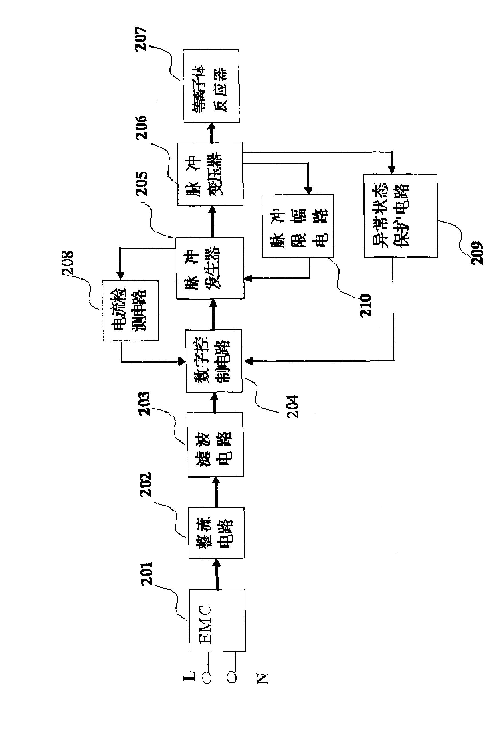
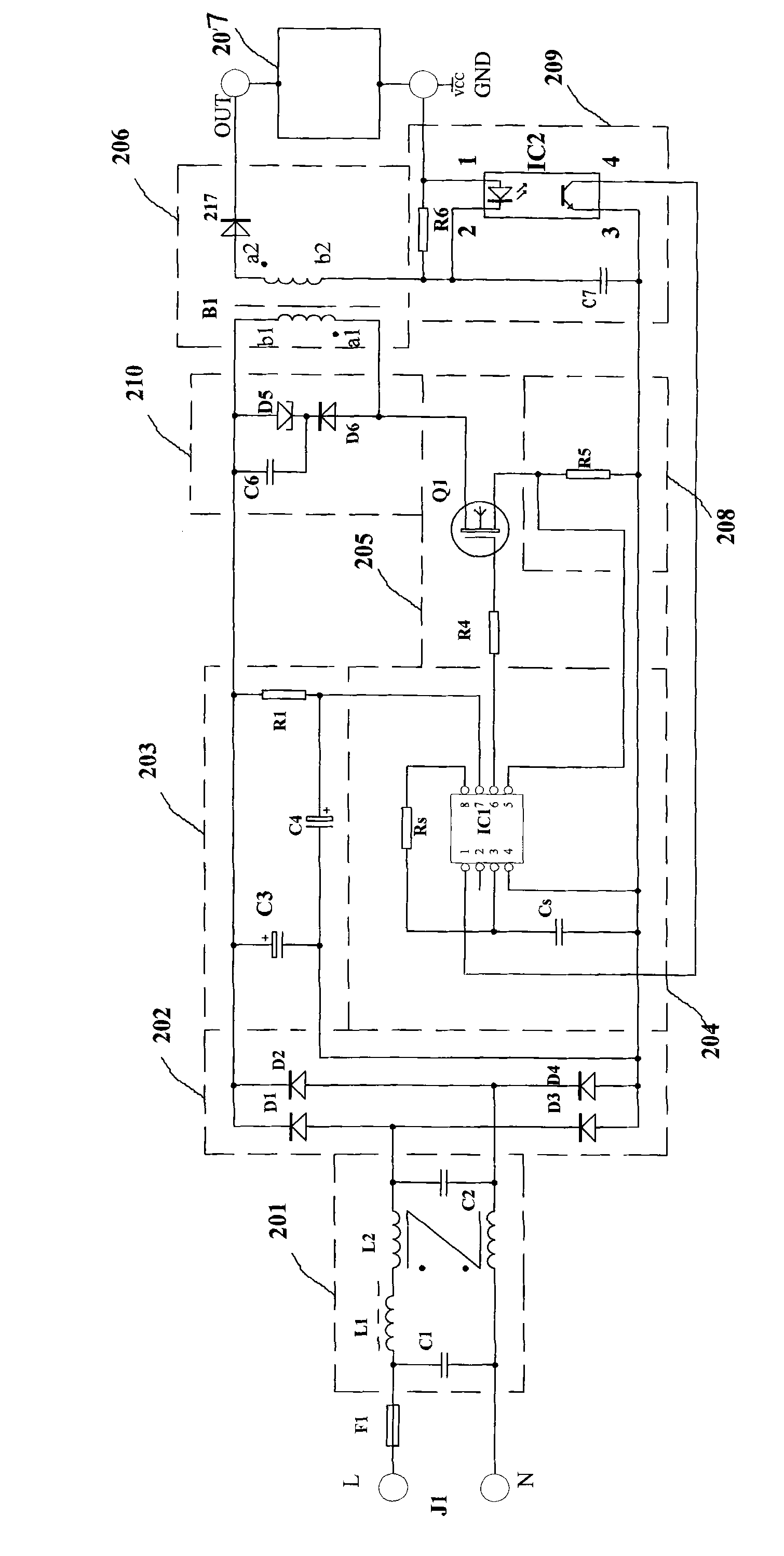
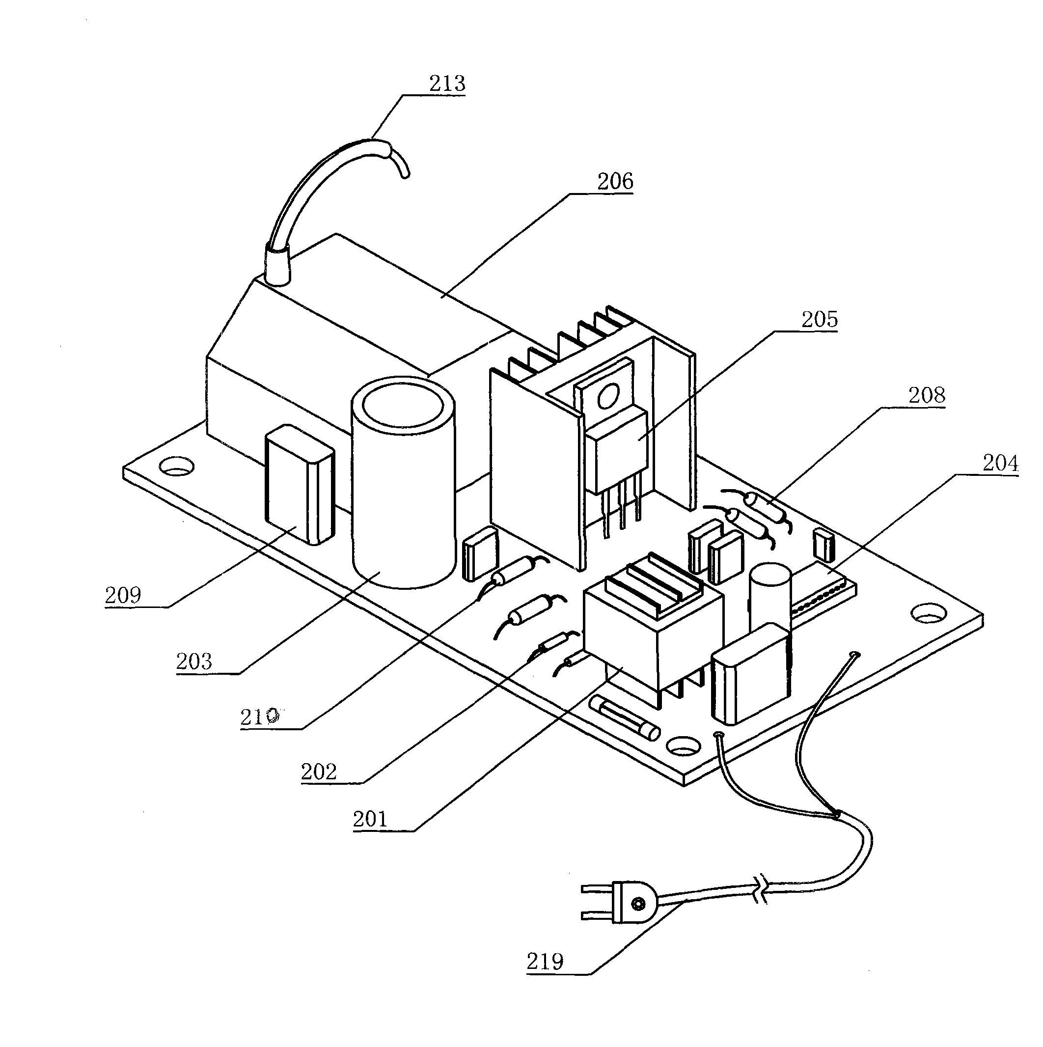
[0050] Reference figure 1 Block diagram of non-thermal plasma pulse power supply, figure 2 Is the electrical principle diagram of the non-thermal plasma pulse power supply of the present invention, image 3 It is a perspective view of the structure of the non-thermal plasma pulse power supply of the present invention.
[0051] The non-thermal plasma pulse power supply of the present invention includes EMC filter 201, rectifier circuit 202, filter circuit 203, digital control circuit 204, pulse generator 205, and pulse transformer 206 for electrical connection in sequence. The output end of pulse transformer 206 is externally connected to plasma Body reactor 207. The output terminal of the pulse generator 205 is provided with a current detection circuit 208, and the detected output current signal of the pulse generator is sent to the oscillator, error amplifier and PWM comparator in the digital control circuit 204, and converted into a digital control current. Output to the input...
Embodiment 2
[0053] Figure 4 It is a schematic diagram of the structure of the pulse transformer of the present invention; Figure 5 It is the circuit structure diagram of the pulse transformer of the present invention. The pulse transformer 206 of the non-thermal plasma pulse power supply of the present invention is provided with a multi-slot insulated bobbin 212, and the secondary coil 215 is wound in three to five sections in the corresponding groove of the multi-slot insulated bobbin 212 Concatenated. The output end of the pulse transformer 206 is provided with a high-voltage wire 213 connected to the anode of the plasma reactor 207. The withstand voltage parameter of the high-voltage fast recovery diode 217 is at least 12KV and the recovery time is less than 80nS; the primary coil 214 is wound in the primary insulated coil frame 211, the primary insulated coil frame 211 and the multi-slot insulated coil frame 212 An iron-based ultramicrocrystalline iron core 216 is provided in the in...
Embodiment 3
[0055] The pulse generator 205 of the non-thermal plasma pulse power supply of the present invention is provided with an insulated gate bipolar transistor Q1, the collector of Q1 is connected to the end a1 of the same name of the primary coil 214, and the emitter of Q1 is connected to the rectifier circuit through the current detection circuit 208 The negative output terminal of 202. The gate of Q1 is connected to the output terminal of the digital control circuit 204 via a resistor R4. The withstand voltage parameter of Q1 is at least 2.7 times the rated value of the input power supply voltage. The insulated gate bipolar transistor Q1 can also be an insulated gate field effect transistor with similar parameters and made by connecting functional pins correspondingly.
[0056] The non-thermal plasma pulse power supply of the present invention is equipped with an inductive energy storage converter, and its working principle: when the switch tube Q1 in the pulse generator 205 is ex...
PUM
| Property | Measurement | Unit |
|---|---|---|
| Saturation magnetic induction | aaaaa | aaaaa |
| Remanence | aaaaa | aaaaa |
Abstract
Description
Claims
Application Information
 - R&D
- Intellectual Property
- Life Sciences
- Materials
- Tech Scout
- Unparalleled Data Quality
- Higher Quality Content
- 60% Fewer Hallucinations
Browse by: Latest US Patents, China's latest patents, Technical Efficacy Thesaurus, Application Domain, Technology Topic, Popular Technical Reports.
© 2025 PatSnap. All rights reserved.Legal|Privacy policy|Modern Slavery Act Transparency Statement|Sitemap|About US| Contact US: help@patsnap.com