Edge-emitting diode semiconductor laser with raster structure
A grating structure, edge-emitting technology, applied in the structure of optical waveguide semiconductors and other directions, can solve the problems of edge-emitting laser threshold characteristics, adverse effects of output mode output power, and uniformity of carrier distribution in the active region. The preparation process is fully compatible, the carrier leakage is reduced, and the preparation process is simple.
- Summary
- Abstract
- Description
- Claims
- Application Information
AI Technical Summary
Problems solved by technology
Method used
Image
Examples
Embodiment 1
[0026] The method for manufacturing edge-emitting semiconductor lasers provided by the present invention is widely applicable to edge-emitting semiconductor lasers of various material systems. The following uses a 980nm InGaAs quantum well edge-emitting semiconductor laser as an example to illustrate its principle.
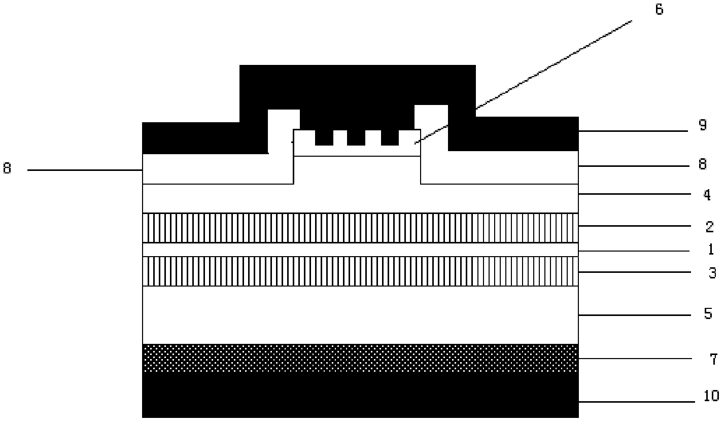
[0027] Such as figure 1 As shown, the structure of an edge-emitting semiconductor laser used to improve the uniformity of carrier distribution in the active region in this embodiment includes:
[0028] A, substrate 7, the substrate 7 is an N-type gallium arsenic material with a thickness of about 300-400um, and the substrate 10 is used for epitaxial growth of various layers of materials of the laser thereon;
[0029] B, N-type confinement layer 5, the N-type confinement layer 5 is made on the substrate 7, and the N-type confinement layer 5 is an N-type AlGaAs material, which can effectively confine the optical field;
[0030] C. The N-type waveguide layer 3 and t...
Embodiment 2
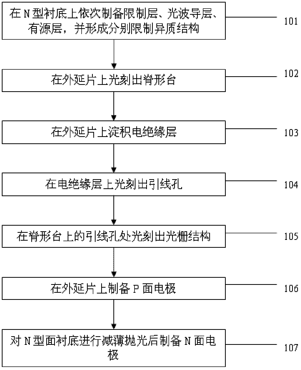
[0036] figure 2 A flow chart of a method for making an edge-emitting semiconductor laser provided by the present invention, the method may include the following steps:
[0037] Step 101: sequentially preparing an AlGaAs confinement layer, an AlGaAs optical waveguide layer, and an InGaAs quantum well active layer on an N-type GaAs substrate, and forming respective confinement heterostructures;
[0038] Step 102: Photocutting the ridge waveguide on the epitaxial wafer;
[0039] Step 103: depositing an electrical insulating layer on the epitaxial wafer;
[0040] Step 104: Photocutting lead holes on the electrical insulating layer;
[0041] Step 105: photoetching a grating structure at the lead hole on the ridge platform;
[0042] Step 106: preparing a P-face electrode on the epitaxial wafer;
[0043] Step 107: Thinning and polishing the N-type substrate and preparing an N-surface electrode;
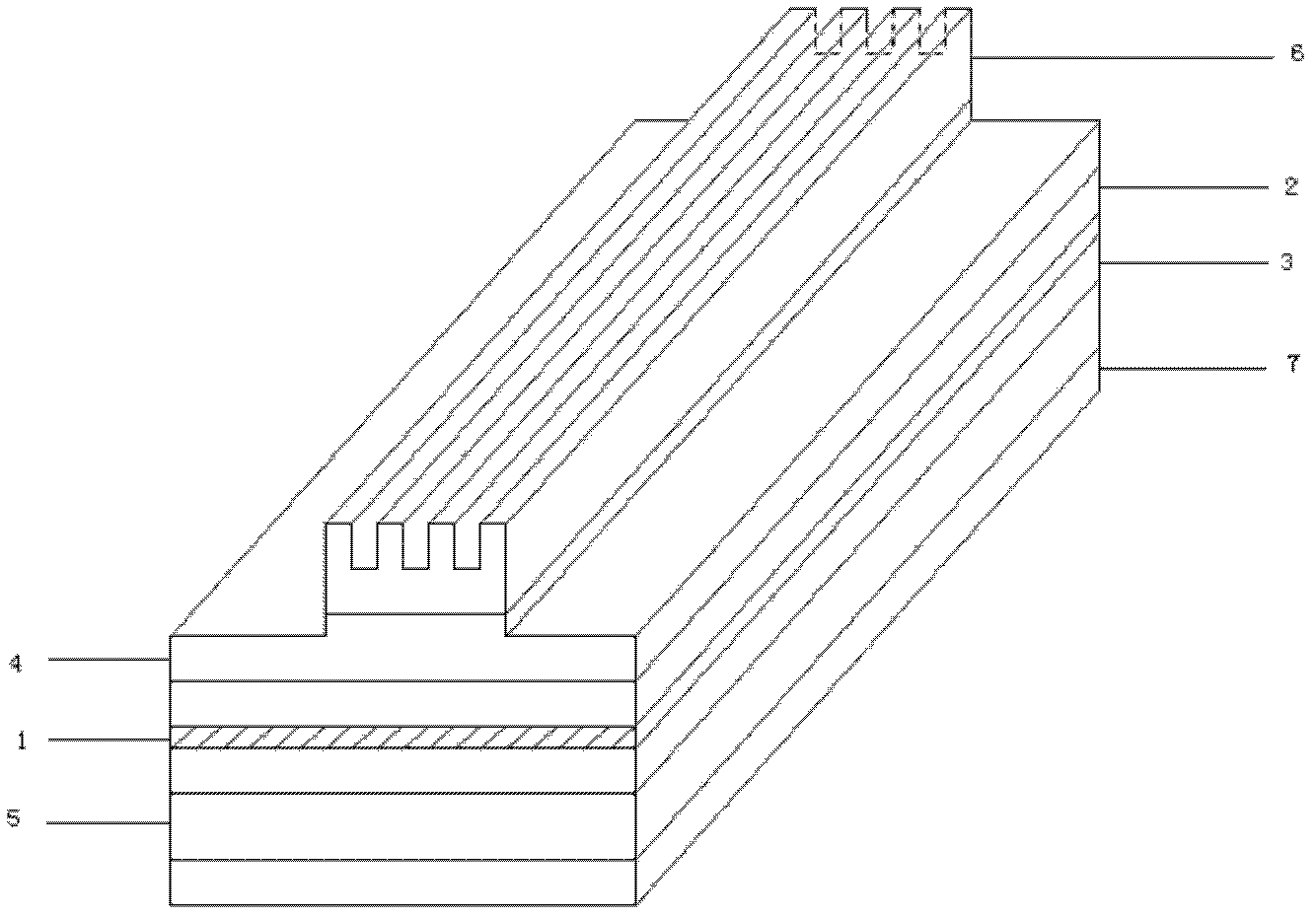
[0044] For the flow chart of the method for making an edge-emitting semiconductor ...
PUM
 Abstract
Description
Claims
Application Information
 - R&D
- Intellectual Property
- Life Sciences
- Materials
- Tech Scout
- Unparalleled Data Quality
- Higher Quality Content
- 60% Fewer Hallucinations
Browse by: Latest US Patents, China's latest patents, Technical Efficacy Thesaurus, Application Domain, Technology Topic, Popular Technical Reports.
© 2025 PatSnap. All rights reserved.Legal|Privacy policy|Modern Slavery Act Transparency Statement|Sitemap|About US| Contact US: help@patsnap.com


