Method for chemically plating nickel on surface of carbon fiber

A surface chemical and electroless nickel plating technology, which is applied in the direction of liquid chemical plating, fiber treatment, metal material coating technology, etc., can solve the problems of low bonding strength of the plating layer, unstable activation solution, complicated operation, etc., and achieve improved hydrophilicity The effect of stability, overcoming instability, and simplifying the operation process

Inactive Publication Date: 2012-08-22
NORTHEAST FORESTRY UNIVERSITY
View PDF3 Cites 43 Cited by
  • Summary
  • Abstract
  • Description
  • Claims
  • Application Information

AI Technical Summary

Problems solved by technology

[0006] The purpose of the present invention is to solve the problems of environmental pollution, unstable activation solution, complex operation and low bonding strength of the obtained coating in the existing carbon fiber surface chemical nickel plating activation method, and provide a method for carbon fiber surface chemical nickel plating

Method used


Image

  • Method for chemically plating nickel on surface of carbon fiber
  • Method for chemically plating nickel on surface of carbon fiber
  • Method for chemically plating nickel on surface of carbon fiber

Examples


specific Embodiment approach 1

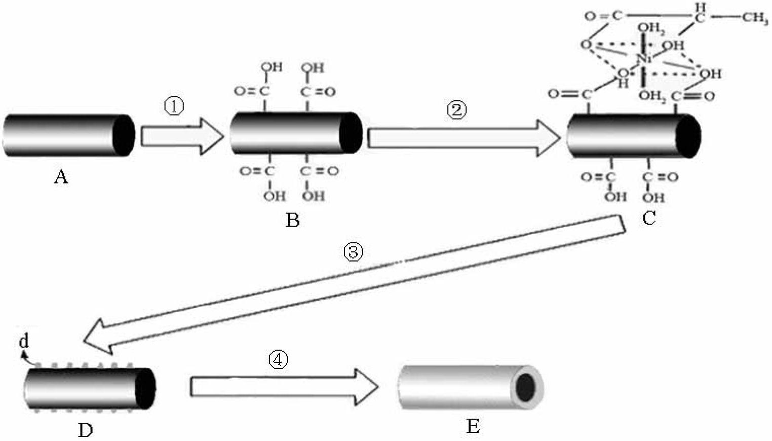
[0010] Specific implementation mode one: this implementation mode is a method for electroless nickel plating on the surface of carbon fiber, specifically completed according to the following steps:

[0011] 1. Surface treatment: ① Degumming: use acetone as solvent, use Soxhlet extraction method to condense and reflux the carbon fiber in a water bath at a temperature of 70℃~80℃ for 12h~48h, and obtain the degummed carbon fiber; ②Degreasing: put The carbon fiber after degumming is placed in a sodium hydroxide solution with a concentration of 0.8mol / L to 1.2mol / L, then boiled for 10min to 20min at a stirring speed of 40rpm to 130rpm, taken out and placed in a concentration 0.8mol / L ~ 1.2mol / L hydrochloric acid solution, and then boiled for 10min ~ 20min at a stirring speed of 40rpm ~ 130rpm, after taking out, the carbon fiber after surface degreasing is obtained; 2. Coarsening treatment: Immerse the carbon fiber after degreasing the surface in concentrated nitric acid, seal it, a...

specific Embodiment approach 2

[0020] Specific embodiment two: the difference between this embodiment and specific embodiment one is: the activation solution described in the step 3 is made of nickel sulfate, sodium acetate, ammonium chloride, sodium hypophosphite, lactic acid, thiourea, ammonia water and Ionized water is mixed; and the concentration of nickel sulfate in the activation solution is 25g / L~35g / L, the concentration of sodium acetate is 15g / L~25g / L, and the concentration of ammonium chloride is 20g / L~30g / L, the concentration of sodium hypophosphite is 25g / L~35g / L, the concentration of lactic acid is 15g / L~20g / L, the concentration of thiourea is 1.5×10 -3 g / L~2.5×10 -3 g / L, the concentration of ammonia water is 45g / L-55g / L; and the pH of the activation solution is 8.0-9.0. Others are the same as the first embodiment.

specific Embodiment approach 3

[0021] Specific embodiment three: the difference between this embodiment and specific embodiment one or two is: the sodium borohydride solution described in step three is formed by mixing sodium borohydride, sodium hydroxide and deionized water; and the The concentration of sodium borohydride in the sodium borohydride solution is 3g / L-4g / L, and the concentration of sodium hydroxide is 8g / L-12g / L. Others are the same as those in Embodiment 1 or 2.


PUM


Abstract

The invention relates to a method for chemically plating nickel on the surface of carbon fiber. The invention aims to solve the problem that the existing method for chemically plating the nickel on the surface of the carbon fiber causes environment pollution, is unstable in activation fluid, complex in operation, and low in plating layer bonding intensity. The method comprises the following steps of: 1, firstly, removing glue and oil from the surface of the carbon fiber; 2, soaking in concentrated nitric acid for coarsening, then washing by distilled water under the help of ultrasound, and finally drying into constant weight, so that the cleaned and coarsened carbon fiber can be obtained; 3, firstly, soaking the obtained product in the activation fluid, then washing by distilled water and soaking in sodium borohydride solution to be reduced, and finally rewashing by distilled water, so that the activated carbon fiber can be obtained; and 4, soaking into chemical nickel-plating liquid, withdrawing, and washing by distilled water, and then drying into constant weight, so that the nickel can be chemically plated on the surface of the carbon fiber. The method for is mainly used for chemically plating the nickel on the surface of the carbon fiber.

Description

technical field [0001] The invention relates to a method for nickel-plating the surface of carbon fiber. Background technique [0002] Carbon fiber is a new type of anisotropic reinforced material with high specific strength (3-7GPa), high specific modulus (200-650GPa), light weight (1.7g / cm 3 ~2.0g / cm 3 ), small coefficient of thermal expansion (0~-1.1×10 6 K -1 ), good mechanical properties (it has a certain reinforcing effect on polymers), fatigue resistance, less carbon spalling and many other excellent properties, which are widely used in the field of composite materials. However, since the carbon and carbon on the surface of the carbon fiber are connected by non-polar covalent bonds, there is a random layer structure of parallel graphite crystallites between the grain boundaries, resulting in poor wettability, poor compatibility with metals, and difficulty in forming Strong interfacial bonding, so carbon fiber has been limited to a certain extent in the field of co...

Claims


Application Information

Patent Timeline
Patent Type & Authority Applications(China)
IPC IPC(8): C23C18/34C23C18/18D06M11/83
Inventor 王立娟颜廷国冯昊
Owner NORTHEAST FORESTRY UNIVERSITY
Why Eureka
Try Eureka