Flue gas desulfurization tower

A desulfurization tower and flue gas technology, which is applied in the directions of air quality improvement, combined device, dispersed particle separation, etc., can solve the problems of increased pressure drop in the operation of the desulfurization system, difficult to eliminate aerosols, and inability to remove them, so as to reduce investment costs. and operating costs, reducing the number of demister stages, and reducing the effect of secondary pollution

Inactive Publication Date: 2012-09-26
浙江菲达环保科技股份有限公司
View PDF4 Cites 13 Cited by
  • Summary
  • Abstract
  • Description
  • Claims
  • Application Information

AI Technical Summary

Problems solved by technology

However, these two flue gas desulfurization process devices still have the following problems: 1) The limestone / lime-gypsum wet desulfurization process usually uses two-layer or three-layer mechanical demisters to remove liquid droplets in the flue gas and reduce water content, but this kind of mist eliminator has poor removal effect on fine liquid droplets, and cannot remove fine dust PM in flue gas 2.5 and heavy metal mercury, etc., resulting in the moisture content in the exhaust smoke, fine dust PM 2.5 and the content of heavy metals is still high; 2) Although the limestone / lime-gypsum wet desulfurization process can efficiently remove SO in the flue gas 2 , but for SO in aerosol form 3 However, the removal rate is very low. Due to the existence of moisture and low temperature in the flue gas emission process, SO 3 It will condense into acid liquid and cause corrosion to the tail flue and chimney; 3) In order to increase the lift height of the flue gas after desulfurization, GGH (flue gas heat exchanger) is usually equipped in the limestone / lime-gypsum wet desulfurization process, Raise the flue temperature of the wet saturated flue gas discharged from the absorption tower to above 80°C, but the installation of GGH will increase the investment and operating costs, and the operating pressure drop of the desulfurization system will increase. , the flue temperature is still lower than its acid dew point, new acid condensation will still occur in the tail flue and chimney, and the corrosion problem still exists; 4) The existing ammonia desulfurization process generally has high ammonia consumption and aerosols that are difficult to eliminate , It is easy to form ammonia mist when exhausting smoke, etc., "NH 3 The cost increase and secondary pollution caused by "escape escape" have become stumbling blocks hindering the development of ammonia desulfurization process in the field of coal-fired flue gas treatment
[0003] With the increasingly stringent environmental standards, PM 2.5 This is better than PM 10 The more harmful particulate matter has become a control indicator, and the US Environmental Protection Agency (EPA) established the PM 10 Added PM to the standard 2.5 emission standards, and stipulates PM 2.5 The three-year average annual concentration of the 3 , the average 24h concentration of 99% in three years is lower than 15μg / m 3 ; my country's newly promulgated "Ambient Air Quality Standards" (GB3095-2012) stipulates that PM 2.5 The primary standard of the annual average concentration is lower than 15μg / m 3 , the secondary standard is lower than 35μg / m 3 , the 24h primary standard of concentration is lower than 35μg / m 3 , the secondary standard is lower than 75μg / m 3 , while the existing electrostatic precipitator or bag filter, electrostatic bag filter humidification desulfurization device is difficult to meet the first-class standard of environmental protection
In addition, the flue gas denitrification technology of thermal power plants in my country mostly adopts the SCR process, which not only has ammonia escape, but also causes SO 3 Acid mist aerosols have increased a lot, and these two aspects, the existing technology does not have a good solution
For the control of mercury and other heavy metals in the flue gas, the activated carbon adsorption technology in the flue is mostly used. This technology not only uses a large amount of activated carbon, but also has very limited adsorption and removal of heavy metals.

Method used


Image

  • Flue gas desulfurization tower
  • Flue gas desulfurization tower
  • Flue gas desulfurization tower

Examples


Embodiment Construction

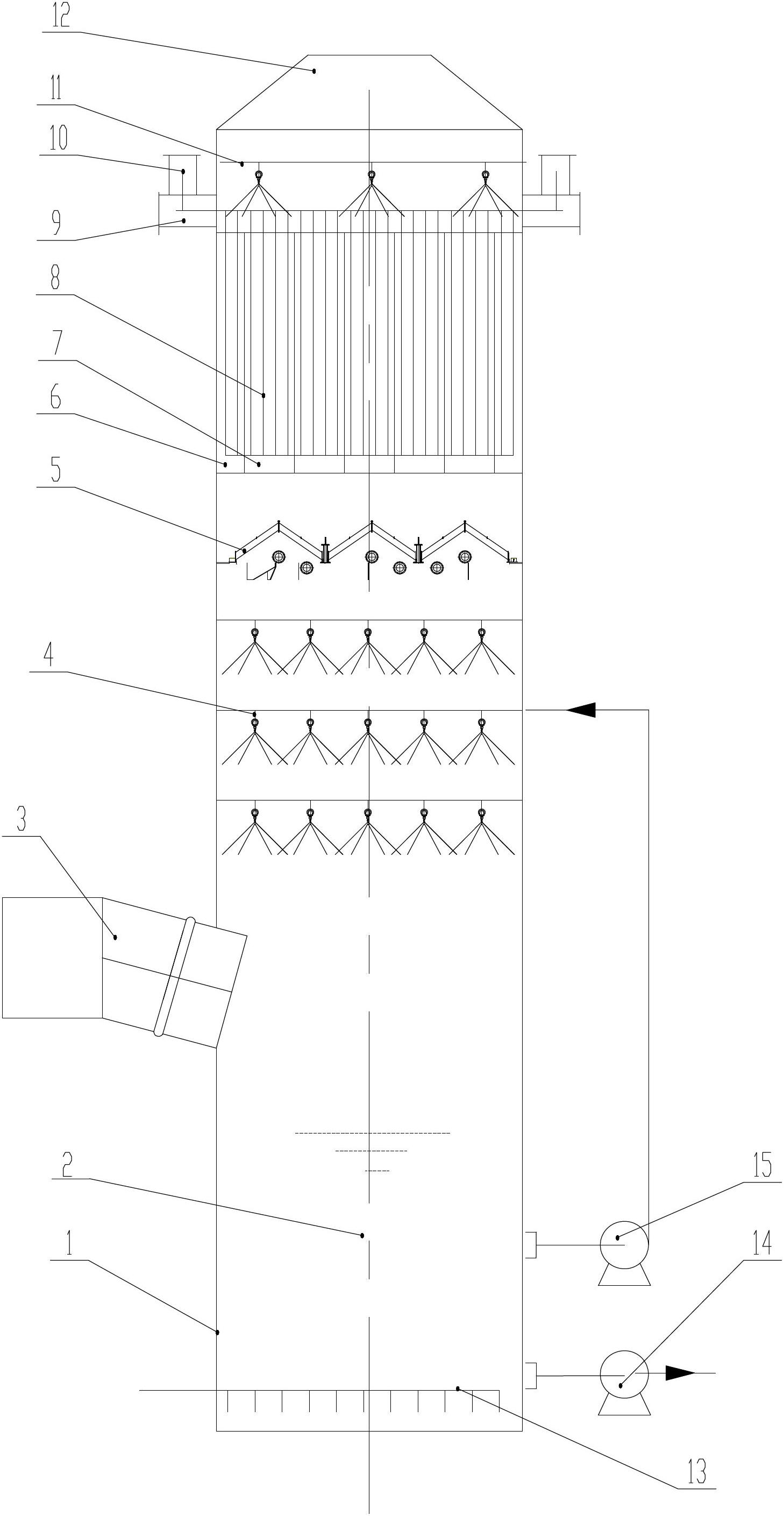
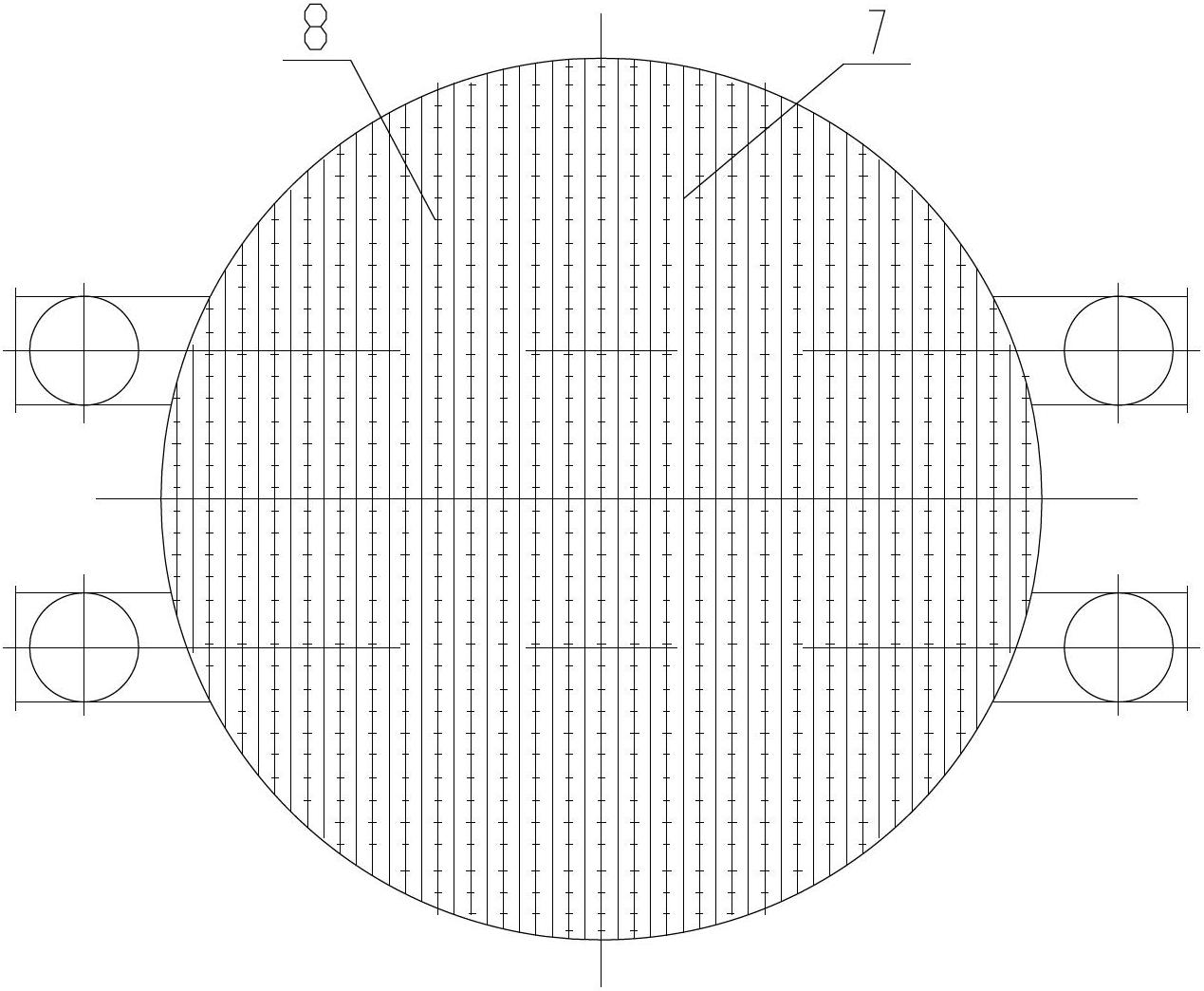
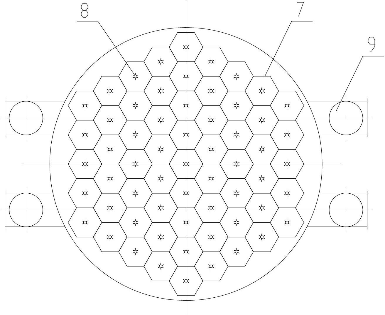
[0016] refer to figure 1 It is an embodiment of a flue gas desulfurization tower of the present invention. A flue gas desulfurization tower includes a tower body 1, and the tower body 1 is sequentially provided with a circulating slurry pool 2, a spray layer 4, a mechanical desulfurization Fogger 5, wet electrostatic precipitator 6, flue gas inlet 3 is set on tower body 1 below spray layer 4, flue gas outlet 12 is set on the top of tower body 1, and said spray layer 4 is provided with three or four stages stage, the circulating slurry pool 2 is connected with a slurry circulating pump 15, and the slurry circulating pump 15 is connected with the spray layer 4, and the wet electrostatic precipitator 6 includes a discharge electrode 8, a dust collecting electrode 7, and a cleaning dust collecting electrode 7 The water film flushing device 11 for dust, the electric control device 10 for powering the discharge electrode 8, the discharge electrode 8 is located above the dust collect...


PUM

PropertyMeasurementUnit
diameteraaaaaaaaaa

Abstract

The invention discloses a flue gas desulfurization tower, which comprises a tower body; a circulating slurry pool, a sprinkler, a mechanical demister, and a wet type electric dust collector. A flue gas inlet is arranged on the tower body below the sprinkler, and a flue gas outlet is arranged at the top end of the tower body. The tower provided by the invention adopts combined wet type electric dust collection and wet desulfurization, employs limestone/lime or other alkaline materials (including ammonia water) as desulfurizer, can effectively solve the problem of NH3 escape existing in the ammonia desulfurization process, reduces secondary pollution, recovers absorbent, reduces ammonia consumption, can not only reduce stages of demisters in the device, but also remove liquid droplets of different particle sizes, PM2.5 fine dust and heavy metal mercury from flue gas, and captures various gases, such as SO3 and NH3, and existing in the form of aerosol in the flue gas.

Description

technical field [0001] The invention relates to a flue gas desulfurization tower. Background technique [0002] Existing flue gas treatment technology cannot remove SO in flue gas more effectively 2 , NO X , acid mist aerosol, mercury, NH 3 , PM 2.5 They can react with each other or other pollutants in the atmosphere to produce serious air pollution, which is also the main source of atmospheric haze. At present, the most widely used and most effective process for flue gas desulfurization is the limestone / lime-gypsum wet desulfurization process. In addition, the ammonia desulfurization process that can make the product resource utilization has also developed greatly in recent years. However, these two flue gas desulfurization process devices still have the following problems: 1) The limestone / lime-gypsum wet desulfurization process usually uses two-layer or three-layer mechanical demisters to remove liquid droplets in the flue gas and reduce water content, but this kind ...

Claims


Application Information

Patent Timeline
Patent Type & Authority Applications(China)
IPC IPC(8): B01D53/80B01D50/00B01D53/64B01D53/50B01D53/58
CPCY02A50/20
Inventor 陈招妹朱建波王剑波赵琴霞戴永阳周超炯尹得仕姚宇平沈志昂郦建国何毓忠潘民兴王飞龙郭峰余顺利
Owner 浙江菲达环保科技股份有限公司
Why Eureka
Try Eureka