Dry distillation device for coal with wide particle size distribution and method

A dry distillation and wide-grain technology, which is applied in the field of coal chemical industry, can solve the problems of high resistance to pyrolysis gas escape, long residence time, and slow heat transfer rate, and achieve improved heat and mass transfer effects, reduced secondary reactions, and uniform heating Improved effect

Active Publication Date: 2012-10-03
INST OF PROCESS ENG CHINESE ACAD OF SCI
View PDF6 Cites 26 Cited by
  • Summary
  • Abstract
  • Description
  • Claims
  • Application Information

AI Technical Summary

Problems solved by technology

[0005] The purpose of the present invention is to overcome the problems of low heat transfer rate and low tar yield and poor quality of pyrolysis gas escape resistance and long residen...

Method used


Image

  • Dry distillation device for coal with wide particle size distribution and method
  • Dry distillation device for coal with wide particle size distribution and method
  • Dry distillation device for coal with wide particle size distribution and method

Examples


Embodiment 1

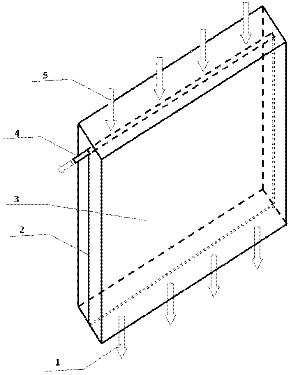
[0046] This embodiment is the pyrolysis of Fugu coal whose particle size is less than 5mm in fixed bed and indirect heating mode, such as figure 1 As shown, there is a pyrolysis gas channel 2 inside the carbonization device, including a coal filling port 5, a combustion heating chamber 3, a pyrolysis gas discharge pipe 4, and a semi-coke discharge port 1. The two walls of the pyrolysis gas channel 2 are connected with the combustion heating chamber 3 parallel. Gas combustion in the combustion chambers on both sides of the dry distillation device provides heat, which is transferred into the pyrolysis coal seam from the combustion heating chamber 3 . The raw coal is loaded into the carbonization device through the coal inlet 5, and the temperature is raised and pyrolysis reaction occurs. The pyrolysis gas phase products enter the pyrolysis gas channel 2 and are finally collected in the pyrolysis gas discharge pipe 4 to be drawn out. After reaching the predetermined reaction tem...

Embodiment 2

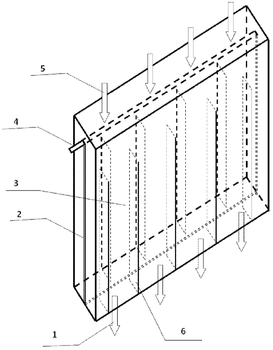
[0049] This embodiment is the pyrolysis of Fugu coal with a particle size of less than 5mm intensified by the plate internals of the fixed bed and indirect heating mode, such as figure 2 As shown, the carbonization device is equipped with a plate-type internal member 6 and a pyrolysis gas channel 2, including a coal inlet 5, a combustion heating chamber 3, a pyrolysis gas discharge pipe 4, and a semi-coke discharge port 1. The plate-type internal member 6 is vertical to the thermal The way of heating the walls and furnace bottom on both sides of the decomposition reactor is placed in the carbonization device, and the pyrolysis gas channel 2 is parallel to the combustion heating chamber 3 and is located between the plate-type inner members 6 at both ends. Gas combustion in the combustion chambers on both sides of the retort device provides heat, which is introduced into the pyrolysis coal seam by the combustion heating chamber 3 and the plate-type internal member 6 . The raw c...


PUM


Abstract

The invention relates to the technical field of coal chemical industry, in particular to a dry distillation device for coal with wide particle size distribution and a method. The dry distillation device for coal with wide particle size distribution, provided by the invention, comprises a semi-coke outlet (1), a combustion heating chamber (3), a coal feed port (5) and a pyrolysis gas discharge pipe (4); two layers of partition plates are also arranged in the dry distillation device; a pyrolysis gas channel (2) is formed between the two layers of partition plates; and pores are formed in the partition plates to form a gas flow path from a fuel bed to the pyrolysis gas channel (2). In the dry distillation device for coal, provided by the invention, an inner component with good heat transfer performance and made from high-temperature resistant material also can be arranged therein, thus the heat transfer of a heating wall on the fuel bed and in the fuel bed is enhanced. In the invention, the pyrolysis gas channel is added into the dry distillation reaction device, so that the gas-phase product generated in the coal dry distillation process can overflow in time; and due to the inner component, the heat transfer and mass transfer effects are improved, the secondary reaction is reduced, and the tar yield and quality are further improved.

Description

technical field [0001] The invention relates to the technical field of coal chemical industry, in particular, the invention relates to a dry distillation device and method for coal with wide particle size distribution. Background technique [0002] Coal pyrolysis is the basic reaction in all coal conversion processes, and the coal tar obtained in this process is the main raw material for the coal chemical industry. At present, the production of coal-based alternative oil, gas and chemicals is mainly based on coal gasification or catalytic liquefaction of coal, but at the same time there is a technical route to produce alternative oil, natural gas and chemicals by using the composition and structural characteristics of coal through pyrolysis. Calculations show that using the volatile matter of coal itself to directly produce fuel oil and gas can improve energy efficiency by 10%-20%, reduce water consumption by 20%-30%, and reduce CO 2 Emission of 0.3-0.9 tons / ton of coal, wh...

Claims


Application Information

Patent Timeline
IPC IPC(8): C10B51/00C10B53/04C10B57/00
Inventor 许光文韩江则武荣成张纯高士秋
Owner INST OF PROCESS ENG CHINESE ACAD OF SCI
Why Eureka
Try Eureka