Polymer solar battery and preparation method thereof

A technology of solar cells and polymers, applied in circuits, electrical components, photovoltaic power generation, etc., can solve the problems affecting the photoelectric conversion efficiency of polymer cells, difficulty in electron transmission, and the disappearance of carrier recombination.

Active Publication Date: 2013-03-06
OCEANS KING LIGHTING SCI&TECH CO LTD +1
View PDF3 Cites 6 Cited by
  • Summary
  • Abstract
  • Description
  • Claims
  • Application Information

AI Technical Summary

Problems solved by technology

The mobility of electrons in polymers is much lower than that of holes, and the location of carrier generation makes the transport distance of electrons in the film longer than that of holes, so the transport of electrons in the film to the Al electrode is

Method used


Image

  • Polymer solar battery and preparation method thereof
  • Polymer solar battery and preparation method thereof
  • Polymer solar battery and preparation method thereof

Examples


preparation example Construction

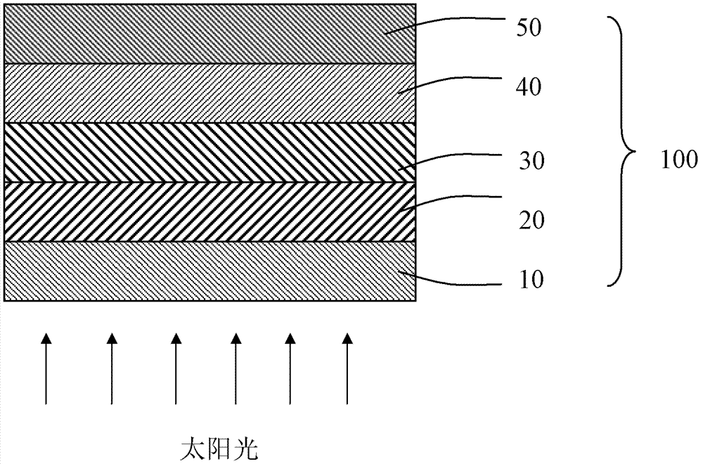
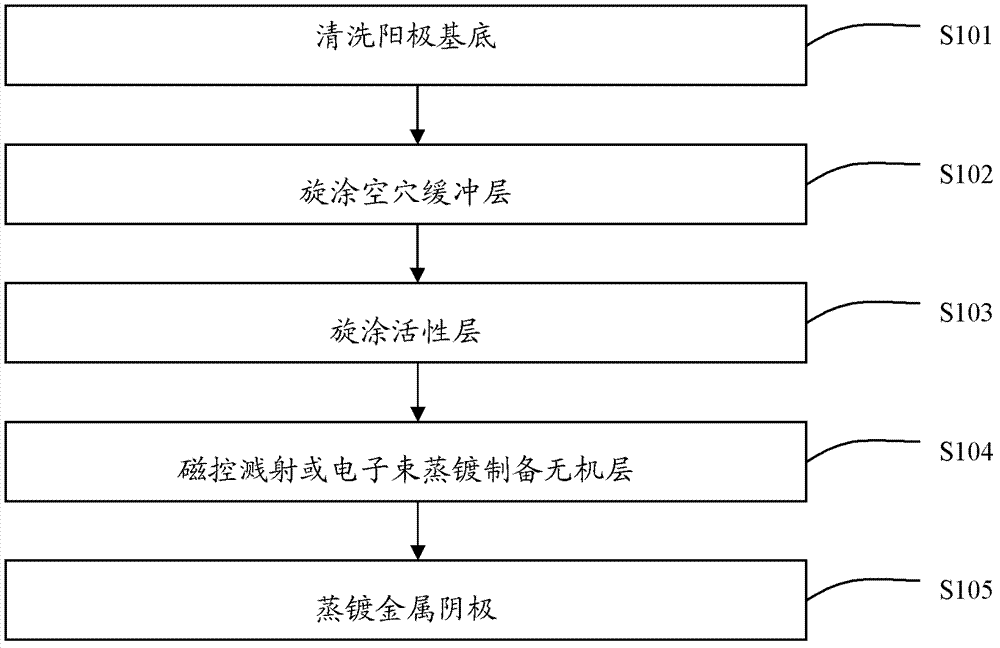
[0035] see figure 2 , the preparation method of the polymer solar cell of one embodiment, comprises the following steps:

[0036] Step S101 , cleaning the anode substrate.

[0037]The anode substrate is preferably indium tin oxide glass (ITO), fluorine doped tin oxide glass (FTO), aluminum doped zinc oxide glass (AZO) or indium doped zinc oxide glass (IZO). Preferably, the anode substrate is first subjected to photolithography treatment, cut into the required size, and then successively use detergent, deionized water, acetone, ethanol, and isopropanol to sonicate for 15 minutes to remove organic pollutants on the glass surface; clean After cleaning, carry out suitable treatment on the conductive substrate, for example: oxygen plasma treatment or UV-ozone treatment. The oxygen plasma treatment time is 5-15 minutes, and the power is 10-50 W; the UV-ozone treatment time is 5-20 minutes.

[0038] Step S102, spin-coating the hole buffer layer.

[0039] Preferably, the PEDOT:PS...

Embodiment 1

[0050] Example 1: First, carry out photolithography treatment on ITO, cut it into the required size, and then use detergent, deionized water, acetone, ethanol, and isopropanol to sonicate for 15 minutes each to remove organic pollutants on the glass surface; clean it up Carry out oxygen plasma treatment to conductive substrate at last, treatment time is 5min, and power is 35W; Chlorobenzene solution, the treatment method is preferably annealing at 200°C for 20 minutes, and the thickness is 120nm.

[0051] Then the electron beam evaporates the inorganic layer, the material is ZnO, and the thickness is 50nm, and then the cathode is evaporated, and the material is Al, and the thickness is 150nm.

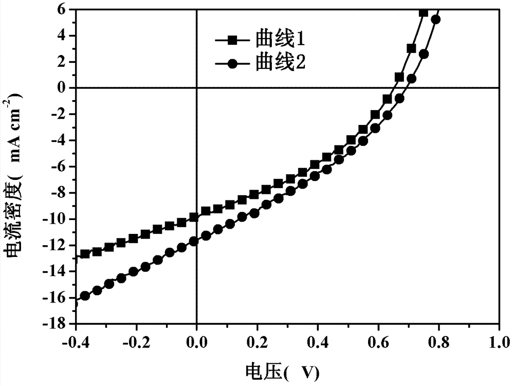
[0052] Please refer to Table 1. Table 1 shows the energy efficiency test data of the solar cell devices prepared in Example 1 and Comparative Example.

[0053] The photocurrent test data of table 1 embodiment 1 and comparative example

[0054]

Current density (mA cm -2 ...

Embodiment 2

[0058] Example 2: First, carry out photolithography treatment on ITO, cut it into the required size, and then use detergent, deionized water, acetone, ethanol, and isopropanol to sonicate for 15 minutes each to remove organic pollutants on the glass surface; clean it Carry out oxygen plasma treatment to conductive substrate afterward, processing time is 10min, and power is 20W; , prepared on conductive glass by spin coating, heated at 100° C. for 15 min after spin coating, and the thickness was controlled at 20 nm. Then spin coat the active layer, the active layer is MDMO-PPV:PCBM system, wherein the solvent of the solution is chloroform. The total concentration of each system was controlled at 8mg / ml, and the mass ratio was in the range of 1:1, then spin-coated in a glove box filled with inert gas, and finally annealed at 200°C for 10min, and the thickness was controlled at 300nm. ; Then the electron beam evaporates the inorganic layer, the material is ZnS, the thickness is ...


PUM

PropertyMeasurementUnit
Thicknessaaaaaaaaaa

Abstract

The invention relates to a polymer solar battery and a preparation method of the polymer solar battery. The polymer solar battery comprises an anode substrate, a cavity buffer layer, an active layer and a metal cathode which are sequentially stacked, and also comprises an inorganic layer arranged between the active layer and the metallic cathode.\The polymer solar battery comprises the active layer/ inorganic layer structure, the distribution of an optical field in the active layer can be improved, so that a generating region of a carrier is changed, a good place is provided for exciton dissociation, and meanwhile, the transmission efficiency of the carrier is improved; and a contacting interface of the active layer and the cathode is separated, so that metal atoms are prevented from diffusing to the active layer to further destroy the structure of the active layer, the role of a buffering layer is played, and the collection efficiency of electrons at the position of the electrode is improved.

Description

【Technical field】 [0001] The invention relates to a polymer solar cell and a preparation method thereof. 【Background technique】 [0002] In 1982, Weinberger et al. studied the photovoltaic properties of polyacetylene and produced the first real solar cell, but the photoelectric conversion efficiency at that time was extremely low (10 -3 %). Immediately afterwards, Glenis and others produced various polythiophene solar cells, but the problems they all faced at that time were extremely low open circuit voltage and photoelectric conversion efficiency. It was not until 1986 that C.W.Tang introduced p-type semiconductor and n-type semiconductor into the double-layer structure device for the first time, which greatly improved the photocurrent. Since then, taking this work as a milestone, organic polymer solar cells have flourished. developed. [0003] In 1992, Sariciftci et al. found that there was a phenomenon of fast light-induced electron transfer in the composite system of ...

Claims


Application Information

Patent Timeline
IPC IPC(8): H01L51/42H01L51/48
CPCY02E10/549
Inventor 周明杰王平黄辉张振华
Owner OCEANS KING LIGHTING SCI&TECH CO LTD
Why Eureka
Try Eureka