Photovoltaic and organic Rankine cycle coupling combined heat and power supply system

A Rankine cycle and combined heat and power technology, applied in the field of energy and environment, can solve the problems of low power generation efficiency, low energy utilization rate, environmental pollution, etc., and achieve the effect of improving power generation efficiency, saving materials and costs, and reducing costs.

Active Publication Date: 2013-03-20
KUNMING UNIV OF SCI & TECH
View PDF7 Cites 25 Cited by
  • Summary
  • Abstract
  • Description
  • Claims
  • Application Information

AI Technical Summary

Problems solved by technology

[0006] The purpose of the present invention is to provide a photovoltaic and organic Rankine cycle coupled heat and power cogeneration system, which uses photovoltaic cells and organic Langcan cycle for comb

Method used


Image

  • Photovoltaic and organic Rankine cycle coupling combined heat and power supply system
  • Photovoltaic and organic Rankine cycle coupling combined heat and power supply system

Examples


Embodiment 1

[0028] Example 1: To build a photovoltaic and organic Rankine cycle coupled heat and power system in a certain area, the power of concentrated photovoltaic power generation is 500kw, the output power of the generator in the high-temperature organic Rankine cycle loop is 300kW, and the low-temperature organic Rankine cycle The output power of the generator in the circuit is 200 kw, the total generating power is 1000kW, and the supply of 45~50℃ sanitary hot water is 75m 3 .

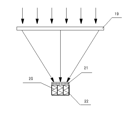
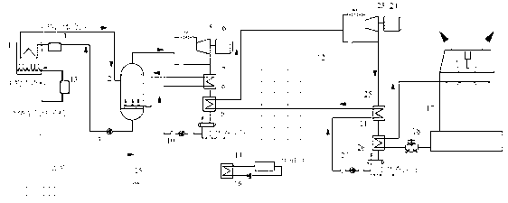
[0029] The photovoltaic and organic Rankine cycle coupled heat and power cogeneration system includes heat transfer fluid circulation loop, biomass combustion furnace smoke exhaust loop, heating hot water loop, cooling loop; one end of biomass combustion furnace exhaust loop and heat transfer fluid circulation The circuit is connected, and the other end is connected to the heating water circuit, which is characterized in that it also includes a high-temperature organic Rankine cycle, a low-temperature organ...

Embodiment 2

[0036] Embodiment 2: This photovoltaic and organic Rankine cycle coupled heat and power cogeneration system is the same as Embodiment 1, and the combustion materials in the biomass combustion furnace 1 used are biodiesel, biomass gasification combustible gas, fuel diesel, heavy oil, Any one or any mixture of methanol, ethanol, methane, natural gas, coal gas, and dimethyl ether.

Embodiment 3

[0037] Example 3: This photovoltaic and organic Rankine cycle coupled heat and power cogeneration system is the same as in Example 1, and the circulating working fluid in the high-temperature organic Rankine cycle loop is R245fa, toluene, butane, isobutane, and pentane , isopentane, cyclopentane, heptane, R113, R11, cyclohexane, benzene, o-xylene, ethylbenzene, 6 methyl 2 siloxane, 8 methyl 3 siloxane, 10 methyl 4 Any one or any mixture of siloxane and 12-methyl-5-siloxane.


PUM

PropertyMeasurementUnit
Generating poweraaaaaaaaaa

Abstract

The invention relates to a photovoltaic and organic Rankine cycle coupling combined heat and power supply system and belongs to the technical field of energy and environment. The photovoltaic and organic Rankine cycle coupling combined heat and power supply system comprises a heat transfer fluid circulation loop, a biomass burner smoke discharge loop, a heat supply hot water loop and a cooling loop, and further comprises a high temperature stage organic Rankine circulation loop, a low temperature stage organic Rankine circulation loop and a solar cell cooler / organic medium preheater. The high temperature stage organic Rankine circulation loop is connected with the heat transfer fluid circulation loop, the low temperature stage organic Rankine circulation loop is connected with the high temperature stage organic Rankine circulation loop, and the cooling loop is connected with the low temperature stage organic Rankine circulation loop. By adoption of a two-stage overlaid type organic Rankine cycle, the photovoltaic and organic Rankine cycle coupling combined heat and power supply system can achieve gradient heat utilization, greatly lower cost, improve utilization efficiency of energy and photovoltaic power generation efficiency, save materials and cost, and facilitate achievement of an individual distributed power generation system.

Description

technical field [0001] The invention relates to a photovoltaic and organic Rankine cycle coupled heat and power cogeneration system, which belongs to the technical field of energy and environment. Background technique [0002] Electricity production plays an increasingly important role in modern production and life. For a century, the power industry has relied heavily on fossil fuels. Although in recent years, with the application of supercritical Rankine cycle and other technologies, the efficiency of coal power has gradually increased (the latest technology in the world can now reach a thermal efficiency of nearly 50%), but power Industry is still the main emission source of serious environmental pollutants such as carbon dioxide and sulfur dioxide. At the same time, with the depletion of fossil fuels, the cost and difficulty of mining will increase. Therefore, we will increase the development of new energy and reduce our dependence on fossil fuels. , using cleaner energy...

Claims


Application Information

Patent Timeline
IPC IPC(8): F01K23/08F01K11/02F24D3/00H01L31/052H01L31/0525
CPCY02E10/50
Inventor 王华葛众王辉涛
Owner KUNMING UNIV OF SCI & TECH
Why Eureka
Try Eureka