Laminated thin film solar cell and manufacturing method thereof

A technology of solar cells and manufacturing methods, applied in the direction of final product manufacturing, sustainable manufacturing/processing, circuits, etc., can solve problems such as battery failure, achieve the effects of simple manufacturing process, enhanced photoelectric function conversion capability, and reduced leakage current

Active Publication Date: 2015-11-11
李毅
View PDF3 Cites 0 Cited by
  • Summary
  • Abstract
  • Description
  • Claims
  • Application Information

AI Technical Summary

Problems solved by technology

However, an important problem faced in mass production is: whether laser or mechanical is used to scribe the P1, P2, P3 channels to form the internal series connection of the battery, the process will affect the cross-section of the transparent conductive film intermediate layer and the back electrode or The front electrodes, including between different stacks, will form conductive channels, resulting in micro-short circuit or leakage, leading to battery (or component) failure

Method used


Image

  • Laminated thin film solar cell and manufacturing method thereof
  • Laminated thin film solar cell and manufacturing method thereof
  • Laminated thin film solar cell and manufacturing method thereof

Examples


example 1

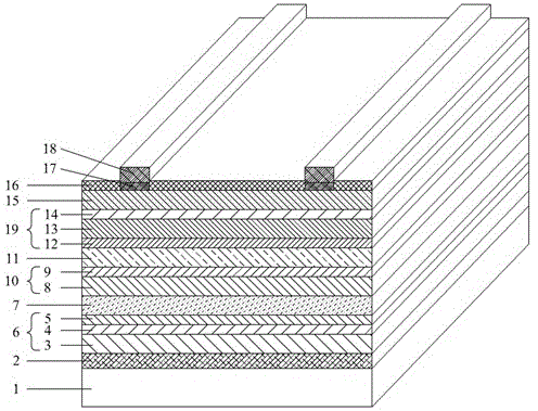
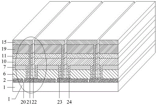
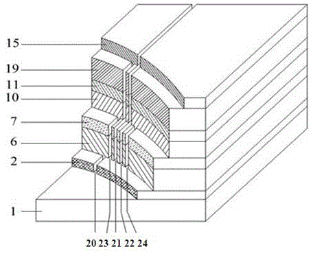
[0051] example 1, figure 2 with diagram 2-1 It is the figure of Embodiment 1 of the present invention

[0052]Using ultra-white glass as the substrate, the copper indium gallium selenide bottom cell is prepared by multi-component co-evaporation three-step method, the cadmium telluride middle cell is prepared by magnetron sputtering method, and the amorphous silicon top cell is prepared by plasma enhanced chemical vapor deposition technology , wherein the first intermediate layer adopts BZO transparent conductive film, and the second intermediate layer adopts silicon oxide low-conductivity transparent film.

[0053] Manufactured as follows:

[0054] Ultra-clear glass is used as the deposition substrate 1 of the three-layer thin-film battery of the present invention. After ultrasonic cleaning and automatic optical detection of defects, DC magnetron sputtering method is used on one side, and by adjusting the pressure of argon gas, the Deposit a layer of high resistance molyb...

example 2

[0079] Ultra-clear glass as the substrate 1, the bottom cell 6 copper indium gallium selenium prepared by multi-component co-evaporation two-step method, the middle cell 10, the cadmium telluride cell was prepared by magnetron sputtering, the amorphous silicon top cell was prepared by plasma enhanced chemistry Manufactured by vapor phase deposition technology, wherein the first intermediate layer is made of silicon oxide low-conductivity transparent film, and the second middle layer is made of AZO transparent conductive film.

[0080] Deposition substrate 1, after ultrasonic cleaning and automatic optical detection of defects, adopts DC magnetron sputtering method on one side, by adjusting the pressure of argon gas, deposits a layer of high resistance molybdenum (Mo) layer under high pressure in sequence, and then Deposit a layer of low-resistance molybdenum (Mo) layer under low pressure, with a total thickness of 1.5 μm, forming the back contact layer 2 of the bottom cell 6; ...

example 3

[0102] Stainless steel is used as the flexible substrate, the copper indium gallium selenide bottom cell 6 is prepared by electrodeposition, the cadmium telluride middle cell 10 is prepared by magnetron sputtering, and the amorphous silicon top cell 19 is prepared by plasma enhanced chemical vapor deposition In the preparation, the first intermediate layer 7 adopts AZO transparent conductive film, and the second intermediate layer 11 adopts silicon oxide low-conductivity transparent film.

[0103] Manufacture takes stainless steel as the substrate 1 of the triple laminated film battery of the present invention, ultrasonically cleans it, adopts DC magnetron sputtering method on its side, and deposits one layer of high-resistance molybdenum (Mo ) layer, and then deposit a layer of low-resistance molybdenum (Mo) layer under low pressure, with a total thickness of 2 μm, forming the back contact layer 2 of the bottom cell;

[0104] The bottom cell is on the back contact layer 2, an...


PUM


Abstract

The invention discloses an efficient and energy saving laminated thin-film solar cell and a manufacturing method, and belongs to the field of solar photovoltaic manufacture. Sensitive cell materials for absorbing blue, green and red light in solar spectra in a matched manner are selected, and the conversion efficiency of a three-junction thin-film cell is close to that of crystal silicon cells by 15%. The forbidden bandwidth of an intrinsic layer of a top amorphous silicon cell is 1.7-1.8eV, the forbidden bandwidth of cadmium telluride of a middle cell is 1.45eV, and the forbidden bandwidth of a copper indium gallium selenium absorbing layer of a bottom cell is about 1.05eV. Middle layers (7 and 11) are introduced to increase a light path, a light trap is formed, and light absorbing efficiency is improved by front and rear shielding wires (23 and 24). Serial short circuit inside a cell module is decreased, and cost and product reject ratio are reduced.

Description

Technical field [0001] The present invention disclosed a kind of amorphous silicon-cadmium cadmium (CDTE)-copper-chopped selenium (CIGS) battery constituted high-efficiency and energy-saving solar cells, which belongs to the field of photovoltaic solar cell manufacturing. Background technique [0002] At present, commercial crystalline silicon solar batteries are the mainstream of the photovoltaic market, and the conversion efficiency of battery components has reached more than 15%.However, the cost and production process have high energy consumption, the space conversion efficiency is limited, and the development is slow.In contrast, thin film solar cells have the characteristics of low cost and environmental friendly.The amorphous silicon battery has become the most mature in the development of the solar cell industry of the silicon-based thin film, and the conversion efficiency has reached more than 10%. The absorption coefficient is 1-2 more than the crystal silicon, and the ...

Claims


Application Information

Patent Timeline
Patent Type & Authority Patents(China)
IPC IPC(8): H01L31/078H01L31/054H01L31/0216H01L31/20
CPCY02E10/50Y02P70/521Y02E10/52Y02P70/50
Inventor 李毅
Owner 李毅
Why Eureka
Try Eureka