Developing roller and imaging device

A developing roller and elastomer technology, applied in corona discharge devices, instruments, electrical components, etc., can solve the problems of poor environmental stability of rubber, large compression set, and poor processability of chloroether rubber, and achieve excellent Environmental stability and voltage stability, avoiding unevenness of printed images, the effect of uniform electrical characteristics

Active Publication Date: 2013-05-15
GUANGDONG LEPUTAI NEW MATERIAL TECH
View PDF4 Cites 5 Cited by
  • Summary
  • Abstract
  • Description
  • Claims
  • Application Information

AI Technical Summary

Problems solved by technology

[0009] 1) The processability of chloroether rubber is very poor, and the compression permanent deformation is large;
[0010] 2) Chlorine ether rubber is the main rubber. Chlorine ether rubber contains chlorine and has high surface free energy. In this way, toner and additives in toner are easy to adhere to the surface of epichloride rubber, and the toner adheres to the developing roller. The surface has little effect on the initial charged image, but as the printing progresses, defects such as ghosts and bottom dust will occur;
[0011] 3) Chlorine ether rubber is a strong polar rubber with ion conductivity, and the environmental stability of the rubber itself is very poor;
[0012] 4), tetrabutylammonium perchlorate or N-butyl-3-methylpyridinium bis(trifluoromethanesulfonyl) imide are very expensive, and tetrabutylammonium perchlorate or N- Butyl-3-methylpyridinium bis(trifluoromethanesulfonyl)imide does not guarantee good environmental stability

Method used


Image

  • Developing roller and imaging device
  • Developing roller and imaging device
  • Developing roller and imaging device

Examples


preparation example Construction

[0035] Regarding the preparation method of the conductive agent, all solid mixing methods are applicable to the present invention, specifically the following steps can be adopted: first, the powder or flake solids of the two components are ground and pulverized on a three-roll machine, and then respectively according to a certain The ratio is such that the two solids can be mixed and ground evenly on a three-roller machine.

[0036] In the preparation process of the conductive elastomer 2 in the developing roller of the present invention, the crosslinking agent can be selected from elemental sulfur, selenium, tellurium, sulfur-containing compounds such as dimorpholine disulfide, dimorpholine tetrasulfide, alkylphenol monosulfide, etc. It can also be organic peroxides such as benzoyl peroxide, di-tert-butyl peroxide, dicumyl peroxide, etc., or quinones, amines, and resinous compounds. These crosslinking agents can be used alone or in combination of two or more.

[0037] In the...

Embodiment 1

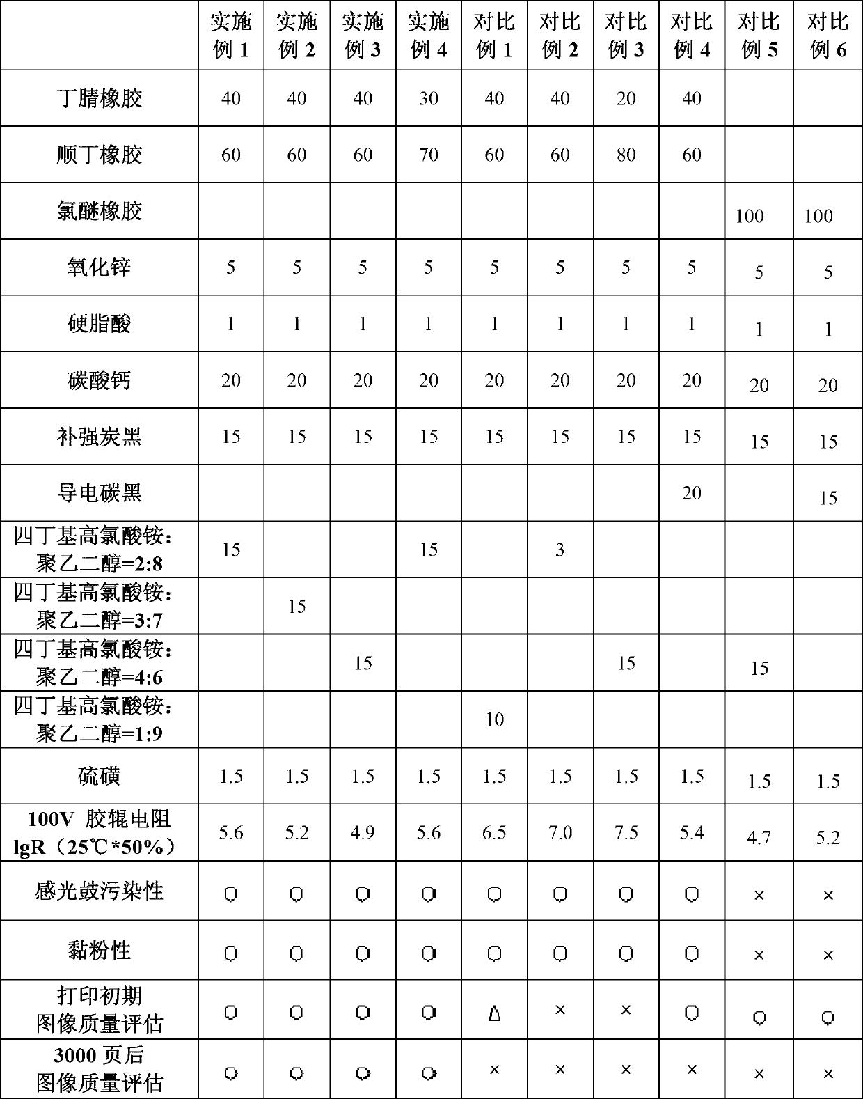
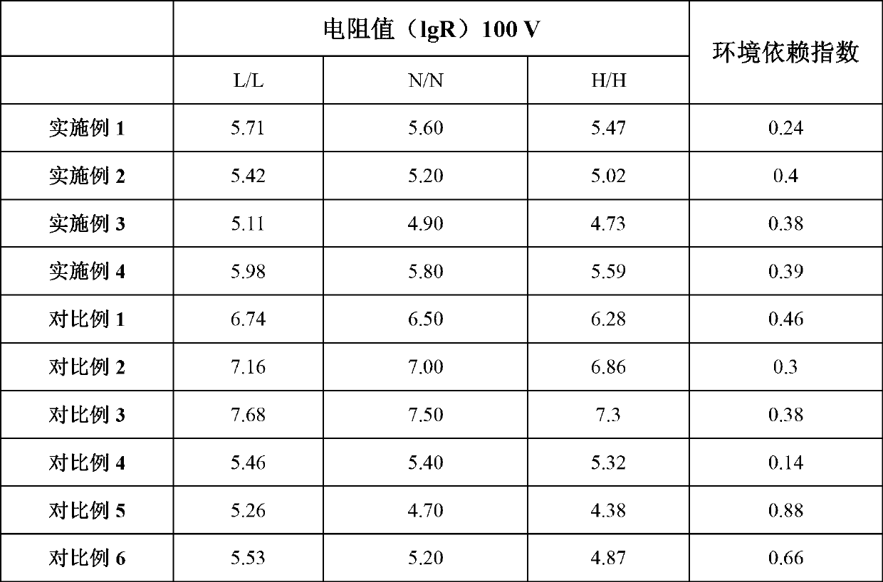
[0046] 40 parts of nitrile rubber, 60 parts of butadiene rubber; 5 parts of zinc oxide, 1 part of stearic acid, 20 parts of calcium carbonate, 15 parts of 1# carbon black (reinforcing carbon black), ion conductive agent (tetrabutyl high Ammonium chlorate:polyethylene glycol=2:8) 10 parts, sulfur 1.5 parts, and they were mixed evenly in an open rubber mixer or a closed rubber mixer to obtain a conductive rubber composition.

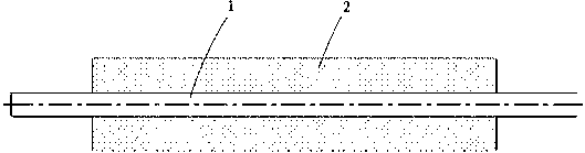
[0047] Then the conductive rubber composition is molded by extruder, and the metal shaft core 1 is inserted in the middle during the molding process to form a rubber roller with a metal shaft core in the middle and a conductive elastomer on the outer layer.

[0048] Finally, put the preformed rubber roller into the vulcanization tank, heat it for 1.5h at 150°C and a pressure of 0.4MPa, and make the rubber roller truly shaped through the vulcanization and cross-linking reaction, and use a grinding wheel to grind off the outer layer of the rubber roller. And...

Embodiment 2

[0050] 40 parts of nitrile rubber, 60 parts of butadiene rubber; 5 parts of zinc oxide, 1 part of stearic acid, 20 parts of calcium carbonate, 15 parts of 1# carbon black (reinforcing carbon black), ion conductive agent (tetrabutyl high Ammonium chlorate:polyethylene glycol=3:7) 10 parts, sulfur 1.5 parts, and they were mixed uniformly in an open rubber mixer or a closed rubber mixer to obtain a conductive rubber composition.

[0051] Then the conductive rubber composition is extruded into shape, and a metal shaft core is inserted in the middle during the molding process to form a rubber roller with a metal shaft core in the middle and a conductive elastic body on the outer layer.

[0052] Finally, put the preformed rubber roller into the vulcanization tank, heat it for 1.5h at 150°C and a pressure of 0.4MPa, and make the rubber roller truly shaped through the vulcanization and cross-linking reaction, and use a grinding wheel to grind off the outer layer of the rubber roller. ...


PUM

PropertyMeasurementUnit
electrical resistanceaaaaaaaaaa
hardnessaaaaaaaaaa

Abstract

The invention provides a developing roller. The developing roller comprises a metal central spindle, and a conductive elastomer covering the metal central spindle, wherein a conductive agent in the conductive elastomer is a mixture containing tetrabutylammonium perchlorate and polyethyleneglycol with an amount being 5% to 50% of weight parts of the conductive elastomer, wherein the ratio of the tetrabutylammonium perchlorate to polyethyleneglycol is equal to 2:8 to 6:4. The invention also provides an imaging device including the developing roller. The developing roller provided by the invention has uniform electric property, can adjust the electric property to obtain uniform resistance, and can ensure that the resistance of the developing roller has low environmental dependency and low voltage dependency, i.e. excellent environmental stability and voltage stability, without increasing hardness of the elastomer. Additionally, the developing roller can prevent the conductive agent from being separated out, and a photosensitive drum is not contaminated, thereby effectively obviating printing defects, such as nonuniform printed images. An imaging apparatus using the developing roller has the advantages of uniform density of printed images, high image quality and high quality.

Description

【Technical field】 [0001] The invention relates to a developing roller, especially a developing roller and an imaging device used in printers and copiers to transfer toner to an electrostatic latent image bearing structure (photosensitive drum) so that the electrostatic latent image forms a visible toner image. 【Background technique】 [0002] Generally, printers and copiers are constructed by carrying an electrostatic latent image (also known as a photosensitive drum), a charging roller that charges the photosensitive drum, a developing roller that transfers toner to the photosensitive drum so that the electrostatic latent image forms a visible toner image, and Toner is composed of conductive rubber rollers such as transfer rollers that are transferred from photosensitive drums to other media. [0003] In recent years, imaging devices represented by printers have been widely popularized in people's daily life, and miniaturization of printers has become a trend. Against this ...

Claims


Application Information

Patent Timeline
Patent Type & Authority Applications(China)
IPC IPC(8): G03G15/08G03G15/02C08L9/02C08L9/00C08L71/08C08K5/04
Inventor 曹方敏佟振双孟鸿李绍昌周宏辉羊辉
Owner GUANGDONG LEPUTAI NEW MATERIAL TECH
Why Eureka
Try Eureka