
Laser induced low pressure jet flow combined etching processing method and device

A technology of laser induction and processing equipment, which is applied in the field of combined processing using laser etching, special processing equipment for this method, water jet processing and chemical corrosion, which can solve the problem that the processing speed cannot meet the requirements, affect the quality of the etched surface, and have no It solves the surface quality problems of micro-cracks and other problems very well, and achieves the effect of good surface processing quality, reducing temperature gradient and avoiding micro-cracks

Inactive Publication Date: 2013-09-25
JIANGNAN UNIV
View PDF7 Cites 19 Cited by
  • Summary
  • Abstract
  • Description
  • Claims
  • Application Information

AI Technical Summary

Problems solved by technology

[0003] At present, the main technical measures for the research on the removal of microcracks, heat-affected zones and slag on the surface of materials at home and abroad include: electrochemical assisted laser processing, water jet guided laser processing, chemical assisted laser processing, subsequent finishing processing, etc. The above research methods , although the etching rate and etching quality of the material have been improved to a certain extent, but if it is used for mass production, there is still a relatively large gap from the actual needs, especially when using this composite processing method for large-scale (such as digital mm or more) processing, the processing speed is far from meeting the requirements; in addition, the etching surface quality is affected because the etching processing products are not easy to remove and re-adhere and deposit on the etching processing surface
These technologies do not solve surface quality problems such as microcracks and slag well.

Method used


Image

  • Laser induced low pressure jet flow combined etching processing method and device

Examples


Embodiment 1

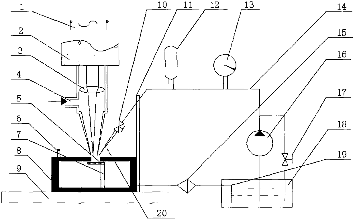
[0019]Embodiment 1: This embodiment is a laser-induced low-pressure jet composite etching processing method. First, a high-energy-density laser beam is used to etch the workpiece, and at the same time, a certain pressure of the corrosive medium solution is used to wash away the slag on the laser processing surface. and corrosion, reducing the roughness of the machined surface. The liquid medium has a cooling effect during processing, and can also reduce the temperature gradient of the processing surface, avoiding microcracks on the processing surface of hard and brittle materials due to thermal stress.

[0020] The corrosion solution is HCl solution or KOH solution, the concentration of HCl solution is 65%; the concentration of KOH solution is 75%, one of them is selected according to the material of the workpiece, and the concentration can be diluted.

Embodiment 2

[0021] Embodiment 2: This embodiment is a laser-induced low-pressure jet composite etching processing device, including an AC power supply 1 and a laser 2, and also includes a focusing lens 3 and an X-Y-Z numerical control workbench 9, and also includes a fluidic device and a workpiece fixture 7, wherein the fluidic device Including corrosive liquid tank 18, plunger high-pressure pump 16, pressure gauge 13, accumulator 12, one-way control valve 10, corrosion-resistant nozzle 20, jet device fixing fixture 11, one end of plunger high-pressure pump 16 is connected to liquid inlet pipe 14 , passes through the pressure gauge 13, flows into the accumulator 12, eliminates the water pressure pulsation, and sprays out through the corrosion-resistant nozzle 20. The fixation and angle change of the corrosion-resistant nozzle are completed by the fixing fixture of the jet device.

[0022] This example also includes a corrosive liquid circulation filtration and return system, which includes...

Embodiment 3

[0025] Embodiment 3: The structure of this embodiment is basically the same as that of Embodiment 2, and the power supply 1 is a three-phase AC power supply.

[0026] When the device of embodiment 2 and embodiment 3 is working, the sealed work box 8 is fixed on the X-Y-Z numerical control workbench 9, the workpiece 5 is fixed on the sealed work box 8 by the workpiece clamp 7, and the X-Y-Z numerical control workbench 9 is controlled by computer according to the regulations. The trajectory movement can ensure that there is relative movement between the workpiece 5 and the laser beam and the jet beam, so that any etching process can be performed. The laser 2 is used for processing, and the relatively high laser energy density is used to directly act on the surface of the workpiece 5 to be etched. Melting, vaporization and jetting occur at the laser action point on the surface of the workpiece 5, thereby forming holes, and then within a short time Almost synchronously with the la...


PUM


Abstract

The invention discloses laser induced low pressure jet flow combined etching processing method and device thereof. The method comprises the following steps: the operations of cutting, drilling and slotting are performed on a workpiece by utilizing high-energy laser beams generated by a laser processing system, and meanwhile erosion is performed on the material surface subjected to laser ablation through high-speed jet flow beams generated by a corrosive medium jet flow device, so that the purpose of removing the material is achieved; the device comprises a laser device and a power source, and further comprises a jet flow generation device and a corrosion liquid circulating reflux device, wherein the jet flow device comprises a corrosion liquid tank, a plunger piston high pressure pump, a pressure gauge, an accumulator, a one-way control valve, a corrosion-resistant spray nozzle and a jet flow device fixed fixture. The method disclosed by the invention has the advantages that the laser ablation is mainly performed, the cooling of high-speed corrosive medium jet flow beams, synchronous erosion and combined processing effect of the cooling and the erosion are added on the basis of the laser ablation, so that the laser induced low pressure jet flow combined etching processing of the material is realized; the invention provides an efficient, clean and combined etching processing process.

Description

1. Technical field [0001] The present invention relates to a method for processing difficult-to-process materials such as millimeter-level cutting, drilling, and slotting, in particular to a composite processing method utilizing laser etching, water jet processing and chemical corrosion, and also relates to a dedicated processing device. 2. Background technology [0002] Water jet processing and laser etching are processing technologies that have gradually matured in the last 30 years. Because of their superior processing advantages, they are widely used in microelectronic device processing, precision machining and other industries. In industries such as electronics and precision machinery, it is often necessary to precisely process various metal and non-metal materials with high hardness, high strength, high toughness and high brittleness, such as fine ceramic quartz, diamond, silicon, and various high alloy steels. These materials are processed. This kind of material is ...

Claims


Application Information

Patent Timeline
Patent Type & Authority Applications(China)
IPC IPC(8): B23K26/14B23K26/36
Inventor 袁根福
Owner JIANGNAN UNIV
Learn More