

Multistage bioleaching reactor process and equipment for sludge treatment
A biological leaching and reactor technology, which is applied in the field of environmental engineering, can solve the problems of increased power consumption, increased operating costs, and increased aeration volume in the biological leaching process, so as to improve oxygen transfer efficiency and improve oxygenation capacity. , the effect of improving the efficiency of dissolved oxygen
- Summary
- Abstract
- Description
- Claims
- Application Information
AI Technical Summary
Problems solved by technology
Method used
Image

Examples
Embodiment 1
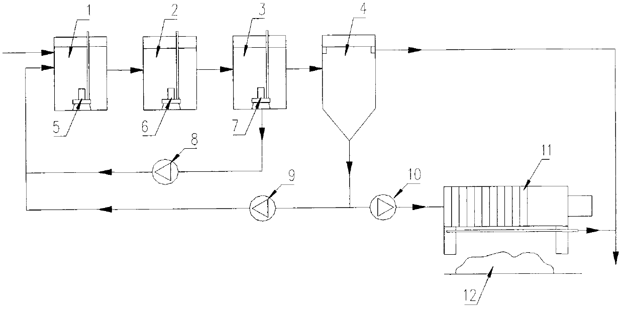
[0024] Example 1: Three-stage bioleaching is used to process 35 tons of municipal sludge every day
[0025] According to the process and equipment mentioned in the present invention, a set of small-scale system for bioleaching treatment of municipal sludge has been established. The three-stage bioleaching reactor is cylindrical, all made of glass fiber reinforced plastics, with a diameter of 3.8 meters and a height of 4.2 meters. , the water depth is 3.5 meters, and a centrifugal diffuse flow aerator is installed inside, each with a power of 1.1 kilowatts, and the total power is 3.3 kilowatts. The upper part of the sludge thickening tank is cylindrical, and the lower part is inverted conical, with a cylindrical diameter of 2.2 meters and a total height of 5.0 meters. A small box-type filter press is used, with a filtration area of 30m 2 . The system can process 35 tons of municipal sludge with a water content of 97% per day, and the chromium content of the original sludge ...
Embodiment 2
[0026] Example 2: Using four-stage bioleaching to process 200 tons of municipal sludge every day
[0027] According to the process and equipment mentioned in the present invention, a reinforced concrete pool is built by combining the four-stage leaching reactor and the sludge thickening tank, which is divided into five compartments. The first four grids are four-stage bioleaching tanks, each grid has an effective volume of 200m 2 , the sludge flows through the first, second, third, and fourth compartments in sequence, and a centrifugal diffuse aerator with a power of 11 kW is installed in the first and second compartments respectively, and the third and fourth compartments A centrifugal diffuse aerator with a power of 7.5 kilowatts is installed in each grid. The fifth cell is the sludge thickening tank with an effective volume of 130m 3 , with a mud bucket at the bottom. Equipped with a filter area of 150m 2 box filter press. The system can process 200 tons of municipal...
PUM
 Abstract
Description
Claims
Application Information