Self-positioning Technology of Plate Bridge Waveguide

A self-positioning and electric bridge technology, applied in the direction of manufacturing tools, metal processing equipment, shearing devices, etc., can solve the problems of shortened service life, long production cycle, large cavity welding deformation, etc., to improve service life, prevent Strong corrosion resistance and the effect of improving production efficiency

Inactive Publication Date: 2015-09-09
CHENGDU JINJIANG ELECTRONICS SYST ENG
View PDF6 Cites 0 Cited by
  • Summary
  • Abstract
  • Description
  • Claims
  • Application Information

AI Technical Summary

Problems solved by technology

This production method has the following disadvantages: ①The processing technology is complicated and the production cycle is long; ②When welding the flanges at both ends of the forming cavity, the two need to be precisely positioned and assembled, and the workload of the operators is heavy, and the skill requirements are relatively high. High; ③ In order to make the brazing filler metal wet, capillary flow, and fill the gap in the base metal, flux is usually used during welding. Due to the use of highly corrosive fluorine-containing flux for multiple flame brazing, residual brazing flux remains in the cavity. It is difficult to completely remove the flux, and the waveguide will be corroded to varying degrees in the future use process, and the service life will be greatly shortened; ④ Affected by local heating, the welding deformation of the cavity is large, and the reactance diaphragm, flange, etc. Component dimensional accuracy is difficult to guarantee

Method used


Image

  • Self-positioning Technology of Plate Bridge Waveguide
  • Self-positioning Technology of Plate Bridge Waveguide

Examples


Embodiment Construction

[0042] The technical solution of the present invention will be further described in detail below in conjunction with the accompanying drawings, but the protection scope of the present invention is not limited to the following description.

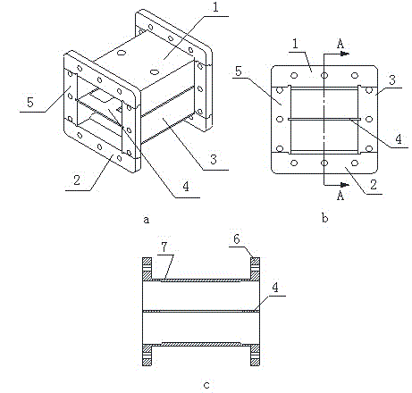
[0043] Such as figure 1 Shown is a slab bridge waveguide fabricated according to the process of the present invention. The plate bridge waveguide self-positioning process includes the following steps:

[0044] (1) Prepare raw materials and complete the preliminary processing of each part of the plate bridge waveguide, including the processing of the upper end plate 1, the processing of the lower end plate 2, the processing of the partition 4, the processing of the left wall plate 5 and the processing of the right wall plate 3 Processing, the flange 6 is respectively formed on the upper end plate 1, the lower end plate 2, the left wall plate 5 and the right wall plate 3;

[0045] (2) Pickle the processed parts separately to remove impuriti...


PUM

PropertyMeasurementUnit
surface smoothnessaaaaaaaaaa

Abstract

The invention relates to a self-positioning process of plate-type electric bridge waveguide, which comprises the following steps: preparing material to complete preliminary processing of each part of the plate-type electric bridge waveguide; conducting surface treatment on each processed part, so as to remove oil stain, impurities and the like on the surface of the part; assembling a left wallboard, a right wallboard, an upper end plate, a lower end plate, a partition board and brazing alloy; placing the assembled plate-type electric bridge waveguide into a vacuum aluminum soldering stove under the matched use of a tooling clamp; conducting vacuum brazing on the plate-type electric bridge waveguide; machining the shape of the plate-type electric bridge waveguide and a flange plate in a numerically controlled manner; drilling through machining; reaming on the flange plate; carrying out electrochemical treatment; rigging. According to the invention, the flange plate is divided into four parts which are formed on the upper end plate, the lower end plate, the left wallboard and the right wallboard respectively, so that the assembly process of the flange plate is eliminated, and the production efficiency is improved; grooves and convex shoulders, which correspond to each other, are formed on the end plates and the wallboards, so that self-positioning assembly is realized, and the cavity assembling precision of the electric bridge waveguide is high; as vacuum brazing is adopted, brazing flux is not required, which avoids corrosion of brazing flux on a cavity, and prolongs the service life of a product.

Description

technical field [0001] The invention relates to a self-positioning technology of a plate bridge waveguide. Background technique [0002] The waveguide is used to transmit ultra-high frequency electromagnetic waves, through which the pulse signal can be sent to the destination with minimal loss, and the inner diameter of the waveguide varies with the wavelength of the transmitted signal. Because of the small loss of waveguide when transmitting electromagnetic waves, it is widely used in radio fields such as centimeter wave and millimeter wave radio communication, radar navigation, etc. [0003] The cross-sectional dimension accuracy, inner surface roughness and geometric accuracy of the waveguide have a significant impact on its performance. The current bridge waveguide manufacturing process used by microwave device manufacturers is usually to divide the standard waveguide into a molded cavity according to the drawings, add reactance diaphragms, flanges and other parts, and ...

Claims


Application Information

Patent Timeline
Patent Type & Authority Patents(China)
IPC IPC(8): B23P21/00B23K1/008B23D31/00
Inventor 凃学明陈忠杨芹粮
Owner CHENGDU JINJIANG ELECTRONICS SYST ENG
Why Eureka
Try Eureka