Conductive nano fluorocarbon coating

A technology of fluorocarbon coatings and conductive nanometers, applied in conductive coatings, anti-corrosion coatings, coatings, etc., can solve the problems of weak conductivity, degradation and cracking, poor high temperature resistance of conductive coatings, etc., and achieve excellent soil resistance, Improved thermal stability and excellent overall performance

Active Publication Date: 2013-12-25
STATE GRID HUNAN ELECTRIC POWER +2
View PDF3 Cites 6 Cited by
  • Summary
  • Abstract
  • Description
  • Claims
  • Application Information

AI Technical Summary

Problems solved by technology

However: 1), most conductive coatings are made of ordinary epoxy resin, polyurethane or acrylic resin, which are prone to aging, degradation and cracking in the soil environment for a long time; 2), commonly used conductive filler graphite powder, aluminum powder, copper powder , Silver powder has the disadvantages of weak conductivity, easy oxidation, and high price; 3) These conductive coatings have poor high temperature resistance, so that they rapidly heat up and fail when the ground network encounters lightning or short-circuit faults, and fail to achieve anti-corrosion effects

Method used


Image

  • Conductive nano fluorocarbon coating
  • Conductive nano fluorocarbon coating
  • Conductive nano fluorocarbon coating

Examples


Embodiment 1

[0022] Example 1: First, the modified carbon nanotubes with a diameter of Ф5nm and a length of 0.1 μm were prepared using the following raw materials and steps:

[0023] (1) Take 16 kg of carbon nanotubes, put them into a propanol solution, prepare a propanol solution with a mass concentration of 2%, oscillate ultrasonically for 20 minutes, and mix evenly to obtain a carbon nanotube mixture;

[0024] (2), according to the weight ratio of 1% of the carbon nanotube mixture obtained in step (1), take the silane coupling agent and put it into deionized water, configure it into an aqueous solution with a mass concentration of 2%, and use oxalic acid to adjust the pH value to 8, Ultrasonic oscillation for 10 minutes to pre-hydrolyze the injected silane coupling agent in deionized water to obtain a hydrolyzed solution of the silane coupling agent;

[0025] (3) Add the silane coupling agent hydrolyzate obtained in step (2) into the carbon nanotube mixture obtained in step (1), stir ev...

Embodiment 2

[0031] Embodiment 2: First, the modified carbon nanotubes with a tube diameter of Ф100 nm and a tube length of 50 μm were produced using the following raw materials and steps:

[0032] (1) Take 30 kg of carbon nanotubes and put them into a butanol solution, prepare a butanol solution with a mass concentration of 8%, oscillate ultrasonically for 40 minutes, and mix evenly to obtain a carbon nanotube mixture;

[0033] (2), according to the weight ratio of 3% of the carbon nanotube mixture obtained in step (1), take the silane coupling agent and put it into deionized water, configure it into an aqueous solution with a mass concentration of 6%, and use oxalic acid to adjust the pH value to 10, Ultrasonic vibration for 30 minutes to pre-hydrolyze the injected silane coupling agent in deionized water to obtain a silane coupling agent hydrolyzate;

[0034] (3) Add the silane coupling agent hydrolyzate obtained in step (2) into the carbon nanotube mixture obtained in step (1), stir ev...


PUM

PropertyMeasurementUnit
diameteraaaaaaaaaa
diameteraaaaaaaaaa
diameteraaaaaaaaaa

Abstract

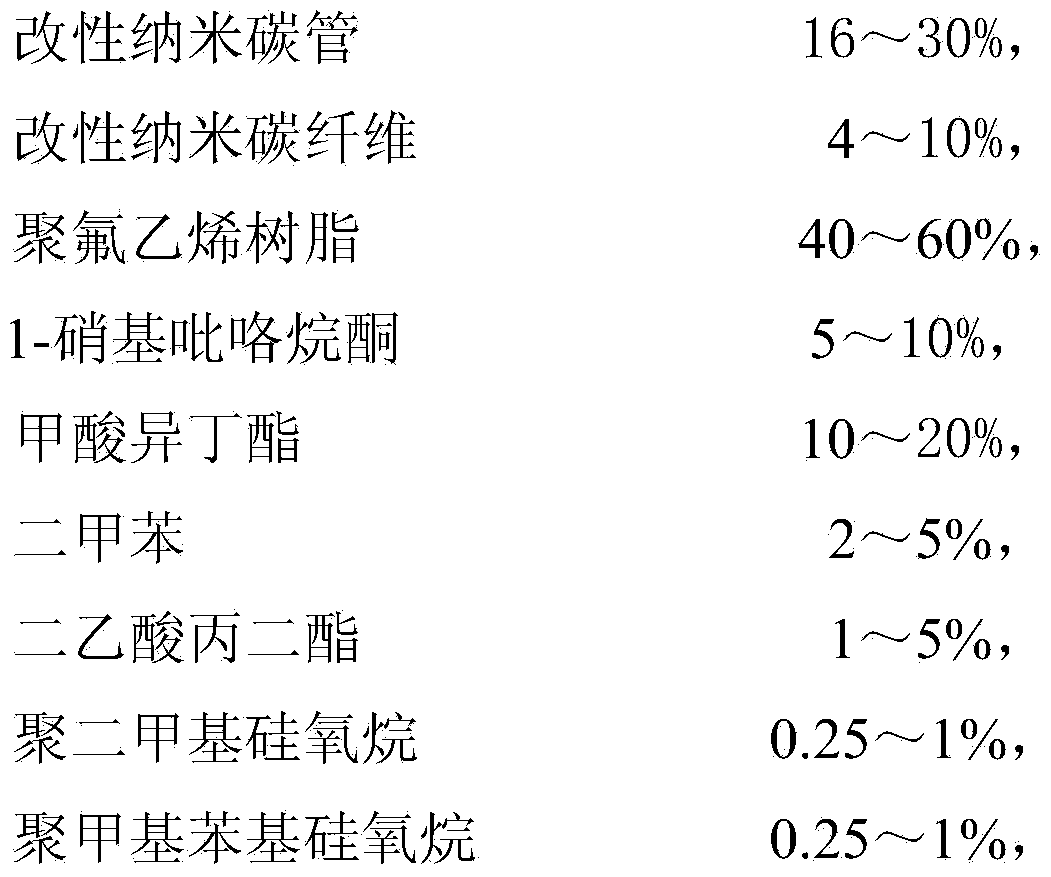
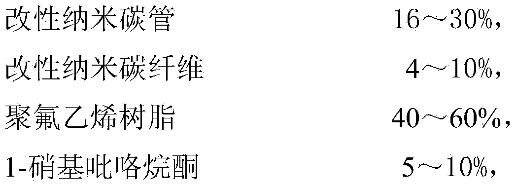
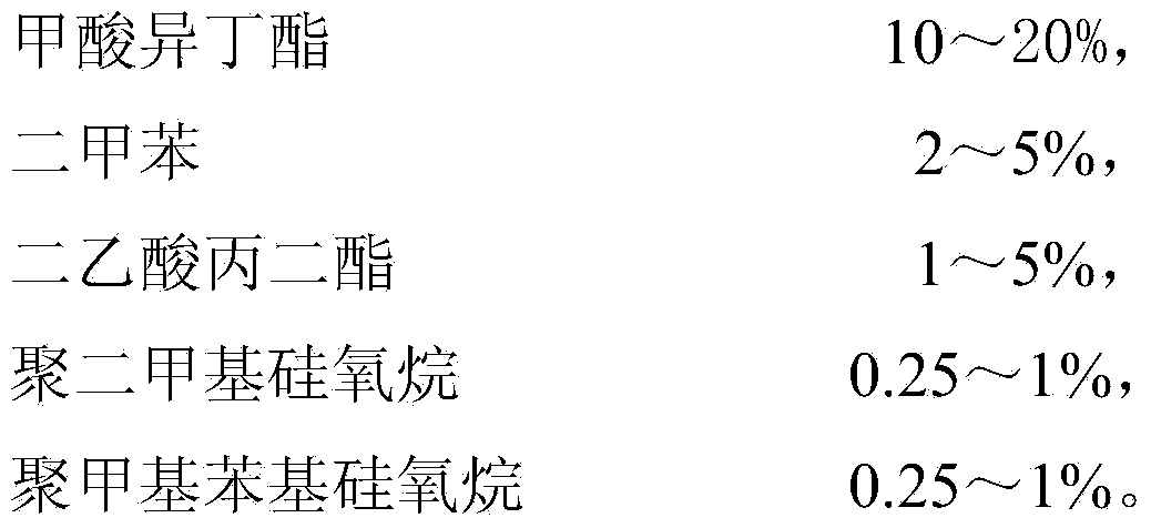
The invention discloses a conductive nano fluorocarbon coating which is prepared by mixing the raw materials by weight percent: 16-30% of modified nanocarbon tube, 4-10% of modified nanocarbon fiber, 40-60% of polyvinyl fluoride resin, 5-10% of 1-nitro-pyrrolidone, 10-20% of iso-butyl formate, 2-5% of dimethylbenzene, 1-5% of propylene diester diacetate, 0.25-1% of polydimethyl siloxane and 0.25-1% of polymethyl phenyl siloxane. The coating has the advantages that (1) the adding quantity of conductive filler reaches up to 40%, so that the adding quantity is greatly increased; (2) the high temperature resistance and the heat stability are greatly improved, so that the coating can endure large current shock; (3) the coating has excellent corrosion resistance and especially can resist the corrosion of acid soil, so that the service life of the coating reaches 20 years; (4) the coating is good in performances and high in cost performance; (5) the coating is widely applied to corrosion prevention of a grounding grid of a large transformer substation.

Description

technical field [0001] The invention belongs to the technical field of anti-corrosion coatings, and more precisely relates to a conductive nano-fluorocarbon coating. Background technique [0002] The grounding grid is mostly made of galvanized carbon steel. This material has been in the complex soil environment for a long time, and it is inevitable to be corroded. Especially in humid and rainy areas, galvanized steel that has been used for 3 to 5 years will be severely corroded or even broken, causing many equipment damages and power outages. Therefore, anti-corrosion of the grounding grid has always been an important research topic in the power system. At present, the commonly used protective measures for the grounding grid are: 1), using copper or copper-clad steel; 2), using the cathode for protection; 3), using a resistance reducing agent Reduce resistance; 4), use conductive paint to conduct electricity. Each of these protective measures has advantages and disadvantag...

Claims


Application Information

Patent Timeline
Patent Type & Authority Applications(China)
IPC IPC(8): C09D127/14C09D7/12C09D5/08C09D5/24
Inventor 徐松冯兵何铁祥胡波涛陆佳政袁新民刘凯郭新茹陈军君王军
Owner STATE GRID HUNAN ELECTRIC POWER
Why Eureka
Try Eureka