Large solar thin film battery piece assembly production process and equipment

A technology of solar thin film and thin film battery, applied in the field of solar battery, can solve problems such as difficulty, small coating area, complicated process, etc., and achieve the effect of keeping clean all the time

Inactive Publication Date: 2014-02-05
JINAN JINGLI NEW ENERGY TECH
View PDF4 Cites 11 Cited by
  • Summary
  • Abstract
  • Description
  • Claims
  • Application Information

AI Technical Summary

Problems solved by technology

[0014] 2. Preparation method of traditional CIGS battery
However, different materials have different vapor pressures, a limitation that makes it difficult to control with arbitrary precision the final composition of the deposited alloy
[0017] 2. Selenization method: This method is to deposit a prefabricated layer of copper indium gallium (Cu-In-Ga) alloy on the deposited molybdenum (Mo) back electrode film, and then pass in hydrogen selenide (H 2 Se) to post-process the copper indium gallium (Cu-In-Ga) alloy prefabricated layer; the selenization method commonly used in the industry has a very complicated process, high selenization temperature (above 550°C), high energy consumption, and low production safety , the excess hydrogen selenide (H 2 Se) gas is difficult to handle, high investment cost, high production cost
[0019] 3. Disadvantages of copper indium gallium selenide thin-film batteries in the prior art: low photovoltaic conversion efficiency, which can reach 12% for advanced manufacturers; small coating area, under the existing technology, the maximum coating area that can be achieved is 600×1000×4mm , the insurmountable technical problem is that with the increase of the coating area, the higher the requirements for coating uniformity, and the existing trimming plate structure cannot meet the needs of large-area coating uniformity

Method used


Image

  • Large solar thin film battery piece assembly production process and equipment
  • Large solar thin film battery piece assembly production process and equipment
  • Large solar thin film battery piece assembly production process and equipment

Examples


Embodiment Construction

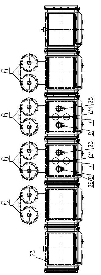
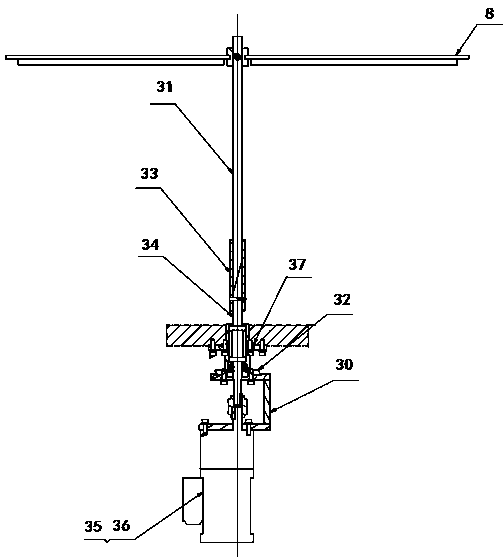
[0046] The specific implementation manners of the present invention will be described below in conjunction with the accompanying drawings. The invention discloses a production process of a large-scale solar thin film cell assembly, which comprises the following steps:

[0047] Ⅰ. Preparation of thin film layer:

[0048] 1) Formation of the molybdenum film layer substrate: on the surface of the substrate, firstly in the 1.5×10 -1 The Mo layer of 0.2-0.5um is evaporated and deposited under the pressure of Pa, so that Mo has a good bonding force with the substrate; -2 Evaporate and deposit a 0.8-1um Mo layer under Pa pressure, and finally form a molybdenum film layer substrate on the substrate;

[0049] 2) The formation of the P-type part in the P-N junction of the thin film battery: at 1.5×10 -3 Under the conditions of Pa pressure and 150-200°C, use electron beams to evaporate the required film material and turn on the corresponding ion source to prepare a copper indium galli...


PUM


Abstract

The invention discloses a large solar thin film battery piece assembly production process and equipment. The process includes the steps of thin film layer manufacturing, line marking, junction, piece compositing, solidification through an autoclave and the like. Under high vacuum or ultrahigh vacuum environment, copper indium gallium selenide (CIGS) is manufactured through electron beam evaporation, an ion source and a correction plate device so as to manufacture a solar thin film battery piece assembly. According to the method, the non-reactive ion source is used, inert gas is added into the vacuum environment to serve as working gas, and the electron beam evaporation mode of vacuum deposition is used for manufacturing a large-area battery piece. A multi-position crucible is used for carrying out time-sharing one-time vacuum evaporation of cadmium sulfide (CdS) or zinc sulfide (ZnS) on a buffering layer and intrinsic zinc oxide (i-ZnO) of a window layer and aluminum-doped zinc oxide (AZO) on a battery substrate to manufacture a copper indium gallium selenide (CIGS) thin film solar battery.

Description

technical field [0001] The invention relates to the technical field of solar cells, in particular to a production process and equipment for a large-scale solar thin film cell assembly. Background technique [0002] Traditional solar cells are divided into crystalline silicon cells and thin film cells, of which crystalline silicon cells are divided into monocrystalline silicon and polycrystalline silicon cells. The photoelectric conversion efficiency of monocrystalline silicon photovoltaic modules is 15-18%, and the photoelectric conversion efficiency of polycrystalline silicon photovoltaic modules is 14%. -17%. Thin-film batteries are divided into amorphous silicon thin-film batteries, CdTe batteries (cadmium telluride thin-film solar cells) and CIGS batteries (copper indium gallium selenide thin-film solar cells). Among the above three thin-film solar cells, CIGS cells have the highest conversion efficiency among thin-film cells. Adding a small amount of gallium can increa...

Claims


Application Information

Patent Timeline
Patent Type & Authority Applications(China)
IPC IPC(8): H01L31/18H01L31/048
CPCY02E10/50H01L31/048H01L31/0749H01L31/18Y02E10/541Y02P70/50
Inventor 黄崇坚
Owner JINAN JINGLI NEW ENERGY TECH
Why Eureka
Try Eureka