Composite membrane for lithium-air battery
A lithium-air battery and composite membrane technology, which is applied to battery components, circuits, fuel cell-type half-cells and primary battery-type half-cells, etc. problems, to achieve excellent mechanical properties, improve cycle stability, reduce corrosion effects
- Summary
- Abstract
- Description
- Claims
- Application Information
AI Technical Summary
Problems solved by technology
Method used
Image
Examples
Embodiment 1
[0040] 1 g of polyethylene glycol (molecular weight 50,000) was dissolved in 25 ml of acetonitrile, 0.32 g of lithium bis(trifluoromethylsulfonyl)imide, 0.05 g of silica nanoparticles (particle size 20 nm) and 0.35 gram of methylbutylpiperidine bis(trifluoromethylsulfonyl)imide salt ionic liquid, stirred at room temperature for 12 hours, and sonicated for 10 minutes to obtain a uniform slurry; next, a polypropylene film (thickness 120 μm, porosity 80%) immersed in the above slurry, take it out after 8 hours, and dry it under vacuum at 50°C for 24 hours.
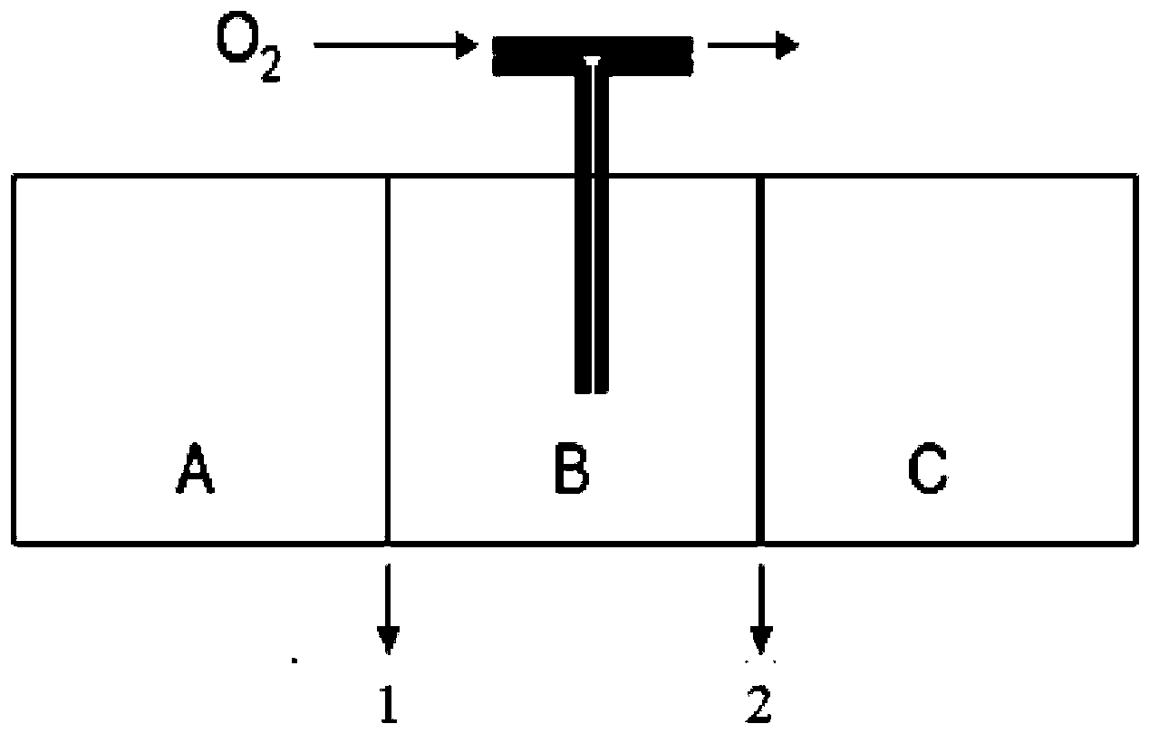
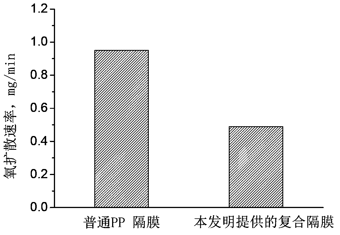
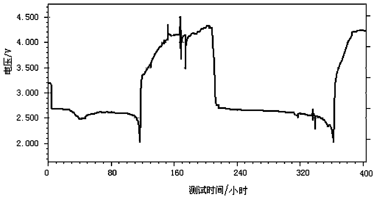
[0041] use Figure 1a The shown setup tests the oxygen permeation properties of the above composite membranes and common polypropylene separators. The device is a closed container, which is divided into three interconnected cavities (A, B and C respectively). The two diaphragms to be compared are placed between the cavities A, B and B, C respectively. Cavities A, B, B, and C are separated by two diaphragms, and under the pro...
Embodiment 2
[0044] 1 g of vinylidene fluoride-hexafluoropropylene copolymer was dissolved in 30 ml of tetrahydrofuran, and 0.3 g of lithium bis(trifluoromethylsulfonyl)imide, 0.02 g of zirconia nanoparticles (particle size 20 nm) and 0.35 gram of methylbutylpiperidine bis(trifluoromethylsulfonyl)imide salt ionic liquid, stirred at room temperature for 12 hours, and ultrasonically treated for 10 minutes to obtain a uniform slurry; next, a piece of polytetrafluoroethylene porous membrane ( Thickness of 120 microns, porosity of 80%) was immersed in the above slurry, taken out after 12 hours, and vacuum dried at 40°C for 24 hours to obtain a composite separator.
[0045] use Figure 1a The oxygen permeation rate of the membrane is tested by the method, and its value is 52% of that of ordinary polypropylene separator.
[0046] The lithium-air battery assembled with this film can run for 3 cycles, and the battery test conditions are the same as in Example 1
Embodiment 3
[0048] 0.5 g of methyl methacrylate was dissolved in 20 ml of tetrahydrofuran, to which 0.3 g of lithium hexafluorophosphate, 0.02 g of manganese dioxide nanoparticles (particle size 10 nm) and 0.35 g of methylbutylpyrrolidine bis(trifluoromethylsulfonium) were added Acyl) imide salt ionic liquid, stirred at room temperature for 15 hours, and ultrasonically treated for 10 minutes to obtain a uniform slurry; The above slurry was taken out after 12 hours, and dried under vacuum at 40° C. for 24 hours.
[0049] The lithium-air battery assembled with the obtained composite film can run for 2 cycles, and the battery test conditions are the same as in Example 1
PUM
| Property | Measurement | Unit |
|---|---|---|
| Particle size | aaaaa | aaaaa |
| Thickness | aaaaa | aaaaa |
| Particle size | aaaaa | aaaaa |
Abstract
Description
Claims
Application Information
 - R&D
- Intellectual Property
- Life Sciences
- Materials
- Tech Scout
- Unparalleled Data Quality
- Higher Quality Content
- 60% Fewer Hallucinations
Browse by: Latest US Patents, China's latest patents, Technical Efficacy Thesaurus, Application Domain, Technology Topic, Popular Technical Reports.
© 2025 PatSnap. All rights reserved.Legal|Privacy policy|Modern Slavery Act Transparency Statement|Sitemap|About US| Contact US: help@patsnap.com


