Electrochemical coupling upflow anaerobic bioreactor and application method

An anaerobic biology and reaction device technology, applied in the field of water treatment, can solve the problems of accelerated reduction and degradation of chlorinated compounds, low utilization efficiency, difficult biodegradation, etc., and achieve the effect of good working performance, reasonable structure and stable operation

Active Publication Date: 2014-05-07
ZHEJIANG UNIV
View PDF7 Cites 10 Cited by
  • Summary
  • Abstract
  • Description
  • Claims
  • Application Information

AI Technical Summary

Problems solved by technology

However, under certain impact load conditions and the influence of toxic substances, anaerobic reactors are prone to acidification phenomena such as increased effluent COD, decreased pH, and reactor sludge floating or washing out, and this phenomenon has long been a UASB phenomenon. One of the limiting factors for popularization and application of a mainstream process
[0003] Chloronitrobenzene is a typical chlorine-containing and nitro-aromatic compound. It has three effects and genotoxicity. It belongs to the first class of priority pollutants stipulated in my country. Stable in nature and difficult to biodegrade, the conventional anaerobic biological treatment process cannot degrade it or the degradation rate is very slow due to the lack of available electron donors
At present, domestic and foreign remediation technologies for such refractory pollutants usually add glycolytic organic matter or substances that can slowl

Method used


Image

  • Electrochemical coupling upflow anaerobic bioreactor and application method
  • Electrochemical coupling upflow anaerobic bioreactor and application method
  • Electrochemical coupling upflow anaerobic bioreactor and application method

Examples


Embodiment 1

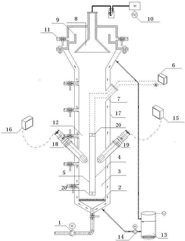
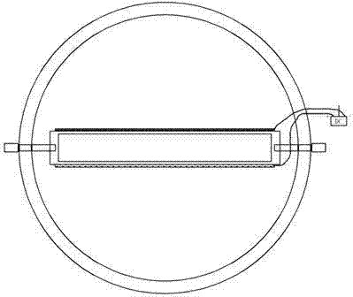
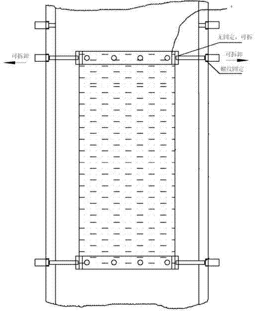
[0031] figure 1 A schematic structural diagram of a novel electrochemically coupled anaerobic reaction device is shown. The device mainly includes a cylindrical upflow anaerobic bioreactor cylinder 12 (anaerobic reactor), in which a water distribution plate 2, a sludge bed 3 and a three-phase separator 8 are sequentially arranged from bottom to top , a pair of bioelectrodes are installed at the bottom of the sludge bed 3 of the anaerobic reactor through a fixture. The shell of the anaerobic reactor is made of organic glass, with an inner diameter of 9cm, a height of 60cm, a total volume of 4.85L, and an effective volume of 4.05L. The bio-electrode pair is composed of a bio-cathode 4 and a bio-anode 5, which are fixed on the anaerobic reactor cylinder through a detachable electrode fixing device, and the corrosion-resistant titanium wire connecting the bio-cathode 4 and the bio-anode 5 passes through the anaerobic reactor cylinder The set wire closed channel 7 is connected to...


PUM


Abstract

The invention relates to an electrochemical coupling upflow anaerobic bioreactor and an application method. The electrochemical coupling upflow anaerobic bioreactor comprises an upflow anaerobic bioreactor cylinder, a biological electrode system and a constant-temperature water-bath system, wherein the biological electrode system is used for supplying electron donors to a microorganism system in the upflow anaerobic bioreactor cylinder, and the constant-temperature water-bath system is used for providing constant-temperature water bath to the upflow anaerobic bioreactor cylinder; a sludge area of the upflow anaerobic bioreactor is provided with a pair of biological electrodes with adjustable electrode area and adjustable inter-electrode distance, the biological electrodes are connected with a direct-current power supply outside a bioreactor main body through a metal conducting wire, and electrode voltage, loop current and cathode potential are monitored and controlled through the direct-current power supply and an electric gauge, which are connected with the outside of the bioreactor main body. By adopting the electrochemical coupling uupflow anaerobic bioreactor, the granulation of the anaerobic sludge can be accelerated, the bioreactor can be rapidly started, and chloronitrobenzene can be stably degraded; moreover, the electrochemical coupling upflow anaerobic bioreactor is reliable in structure, easy to machine, small in energy consumption and stable in running.

Description

technical field [0001] The invention relates to a novel electrochemical coupling anaerobic biological reaction device and method, belonging to the technical field of water treatment. Background technique [0002] In the field of wastewater biological treatment, anaerobic biological treatment technology has a wide range of applications, low operating energy consumption, high volume load, low sludge production, and biogas production capacity. It is one of the most widely used processes in wastewater treatment processes. Anaerobic biological treatment process from the initial septic tank to the subsequent development of anaerobic biological filter, anaerobic contact method, segmented anaerobic treatment method, sludge expanded bed and anaerobic fluidized bed, anaerobic biological turntable, etc., Rapid development and wide application. Among them, the upflow anaerobic sludge bed reactor (UASB) has become the mainstream process device for anaerobic biological treatment because ...

Claims


Application Information

Patent Timeline
IPC IPC(8): C02F3/28C02F1/46
Inventor 朱亮高凯拓徐向阳戚娇琴
Owner ZHEJIANG UNIV
Why Eureka
Try Eureka