
Titanium alloy thin-wall blade laser-cladding low-stress local orientation cooling restoration method

A technology of laser cladding and directional cooling, which is applied in the field of laser cladding low-stress local directional cooling repair of titanium alloy thin-walled blades. Overheating, over-burning, loss of burn-through strength, and little effect, etc., to achieve uniform microstructure, improve the quality of repair molding, and reduce the effect of the affected area

Inactive Publication Date: 2014-09-17
XI AN JIAOTONG UNIV
View PDF4 Cites 5 Cited by
  • Summary
  • Abstract
  • Description
  • Claims
  • Application Information

AI Technical Summary

Problems solved by technology

[0006] At present, the method of mechanical clamping is mainly used to prevent heat deformation of thin-walled parts, which makes the tooling very complicated and difficult to implement, and this method cannot prevent thin-walled parts from being overheated, over-burned, burn-through and caused by The decrease in strength and other properties caused by this
The commonly used cooling technology room uses the principle of material heat capacity to absorb heat, and dissipates heat and cools down through the convection of gas and liquid media, heat conduction, etc. Since the isobaric heat capacity of materials is mostly in the range of 20 to 40Jk -1 mol -1 However, the heating in the laser cladding process has the characteristics of unsteadiness and intensity, and the effect of cooling the blades by this method is not great, and it is difficult to effectively prevent thin-walled parts from being overheated, deformed, over-burned and burnt. Put on

Method used


Image

  • Titanium alloy thin-wall blade laser-cladding low-stress local orientation cooling restoration method
  • Titanium alloy thin-wall blade laser-cladding low-stress local orientation cooling restoration method

Examples


Embodiment 1

[0038] 1) Mix iron powder with a particle size of 50-100 μm and water glass evenly according to a mass ratio of 3:1 to obtain an iron powder mixture;

[0039] 2) Paste the iron powder mixture on the damaged titanium alloy thin-walled blade, wherein the diameter of the defect repair point is ≤10mm, and the iron powder mixture is pasted at a distance of 3mm from the defect repair point of the titanium alloy thin-walled blade, in a circular distribution, and the defect repair point The ratio of the area to the paste area of ​​the iron powder mixture is 1:1;

[0040] 3) Put the titanium alloy thin-walled blade pasted with the iron powder mixture into a glove box filled with inert gas, and use a powder feeder to transport the titanium alloy powder for repair to the titanium alloy thin-walled blade at a speed of 30g / min. At the defect repair point, a laser with a power of 2000W is used to emit a laser with a spot diameter smaller than or equal to the diameter of the defect repair po...

Embodiment 2

[0043] 1) According to the mass ratio of 5:1, the iron powder with a particle size of 150-200 μm and the paraffin-based binder are uniformly mixed to obtain an iron powder mixture;

[0044] 2) Paste the iron powder mixture on the damaged titanium alloy thin-walled blade, wherein the diameter of the defect repair point is ≤10mm, and the iron powder mixture is pasted at a distance of 8mm from the defect repair point of the titanium alloy thin-walled blade, in a circular distribution, and the defect repair point The ratio of the area to the paste area of ​​the iron powder mixture is 1:2;

[0045] 3) Put the titanium alloy thin-walled blade pasted with the iron powder mixture into a glove box filled with inert gas, and use a powder feeder to transport the titanium alloy powder for repair to the titanium alloy thin-walled blade at a speed of 120g / min. At the defect repair point, a laser with a power of 2000W is used to emit a laser with a spot diameter smaller than or equal to the ...

Embodiment 3

[0048] 1) According to the mass ratio of 4:1, the iron powder with a particle size of 100-150 μm and the polymer binder are uniformly mixed to obtain an iron powder mixture;

[0049] 2) Paste the iron powder mixture on the damaged titanium alloy thin-walled blade, wherein the diameter of the defect repair point is ≤10mm, and the iron powder mixture is pasted at a distance of 5mm from the defect repair point of the titanium alloy thin-walled blade, in a circular distribution, and the defect repair point The ratio of the area to the sticking area of ​​the iron powder mixture is 1:1.5;

[0050] 3) Put the titanium alloy thin-walled blade pasted with the iron powder mixture into a glove box filled with inert gas, and use a powder feeder to transport the titanium alloy powder for repair to the titanium alloy thin-walled blade at a speed of 80g / min. On the defect repair point, a laser with a power of 2000W is used to emit a laser with a spot diameter smaller than or equal to the dia...


PUM

PropertyMeasurementUnit
Particle sizeaaaaaaaaaa

Abstract

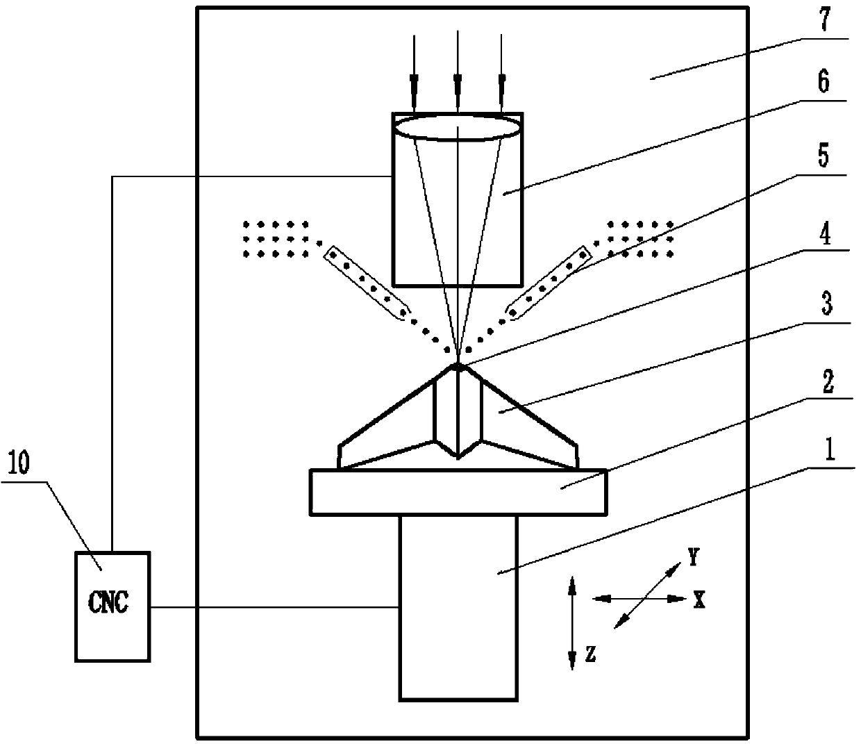
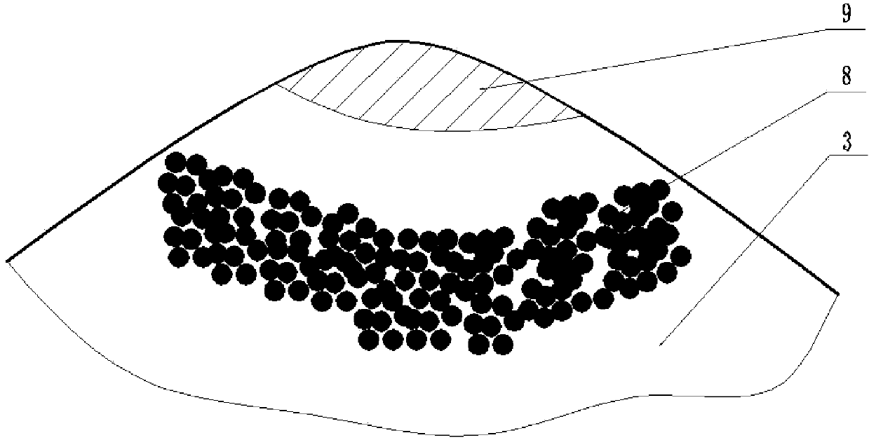
The invention discloses a titanium alloy thin-wall blade laser-cladding low-stress local orientation cooling restoration method. A certain amount of iron powder is previously bonded around the thin-wall blade defect restoration point, high temperature generated in the laser cladding process is utilized to melt the titanium alloy powder by utilizing the metal melting phase-change latent heat unsteady-state partial high-efficiency heat absorption principle, and heat is conducted to the periphery of the thin-wall blade so as to melt the iron powder; and the melting of the iron powder needs to absorb abundant heat, thereby lowering the superheating, deformation, overburning and burnout in the thin-wall blade cladding process. Meanwhile, since the iron powder is subjected to local orientation cooling, the influence area is small, the microstructure of the cladding layer is uniform, and the grains are refined, thereby obviously reducing the internal stress and cracks and effectively enhancing the restoration forming quality of the titanium alloy thin-wall blade; and the cladding layer has the advantages of higher hardness than the plasma cladding layer, small stress strain, fewer cracks and pores and high bonding strength.

Description

technical field [0001] The invention belongs to the field of laser cladding additive manufacturing, and relates to a low-stress local directional cooling repair method for laser cladding of titanium alloy thin-walled blades. technical background [0002] Titanium alloy has the advantages of high specific strength, good high and low temperature performance, and corrosion resistance. It is widely used in the aerospace field and is the preferred material for structural parts such as aviation blades. However, its wear resistance is poor, and the blades of aviation compressors are often seriously damaged due to vibration friction, sand impact and other reasons. [0003] Common methods for repairing blade surface defects include welding (including laser welding, arc welding, flame welding, electron beam welding, plasma welding, vacuum brazing, and tungsten inert gas (TIG) welding, etc.), thermal spraying (including plasma Spraying, flame spraying, arc spraying, detonation sprayin...

Claims


Application Information

Patent Timeline
IPC IPC(8): C23C24/10
Inventor 魏正英杜军卢秉恒陈祯赵光喜
Owner XI AN JIAOTONG UNIV
Learn More