Sintering energy-saving technique and system capable of removing multiple pollutants

A pollutant removal technology, applied in the direction of dispersed particle separation, air quality improvement, chemical instruments and methods, etc., can solve the problem of not being able to properly divide the concentration area of ​​pollutants, and failing to make good use of sintering machine head smoke Gas waste heat, can not be well dealt with and other issues, to achieve the effect of reducing initial investment and operating costs, compact structure, and reduce production

Inactive Publication Date: 2014-12-10
ZHEJIANG UNIV
View PDF8 Cites 48 Cited by
  • Summary
  • Abstract
  • Description
  • Claims
  • Application Information

AI Technical Summary

Problems solved by technology

[0006] The low-energy sintering flue gas nitrogen oxide emission reduction system and method provided by the patent document with the publication number CN101829481A, uses a part of the flue gas with a high concentration of nitrogen oxides in the middle section of the sintering bellows for denitrification treatment, and part of it is used for cyclic sintering. However, this patent does not deal with other pollutants such as sulfur dioxide, and also fails to make good use of the waste heat of the flue gas from the sintering head;
[0007] And, the invention patent with publication number CN101376921A proposes a process for reducing sulfur dioxide emission in sintering fl...

Method used


Image

  • Sintering energy-saving technique and system capable of removing multiple pollutants

Examples


Embodiment Construction

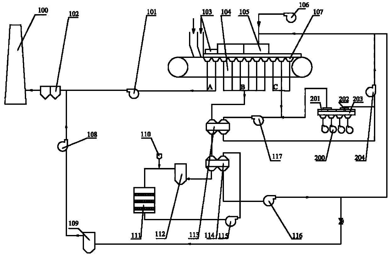
[0039] Such as figure 1 As shown, the sintering energy-saving and multiple pollutants removal system in this embodiment includes a sintering machine 104, a sintering bellows 107, an ignition device 103, a circulating fume hood 105, a blower 106, a section A induced draft fan 101, a chimney 100, Bag dust collector 102, rotary preheater 113 and rotary preheater 114, afterburner burner 112, ammonia injection device 110, SCR denitrification device 111, desulfurization device 109, B-section induced draft fan 115, B-section circulation fan 116 , C section induced draft fan 117, sintering cooler 203, cooler high temperature section 201, cooler low temperature section 202, cooler blower 200, low temperature section circulation fan 204 and induced draft fan 108.

[0040] The sintering bellows 107 are located at the lower part of the sintering machine 104. According to the concentration distribution of pollutants produced during iron ore sintering, the sintering bellows 107 are divided ...


PUM


Abstract

The invention discloses a sintering energy-saving technique capable of removing multiple pollutants. Flue gas discharged by a sintering wind box on the lower part of a sintering machine is sequentially divided into section A flue gas positioned at the head of the sintering machine, section B flue gas positioned in the middle of the sintering machine, and section C flue gas positioned at the tail of the sintering machine; the section A flue gas is discharged after being subjected to dust removal treatment; and the section C flue gas is used for preheating the section B flue gas, the preheated section B flue gas is denitrified and divided into two parts, one part is discharged after being subjected to desulfurization treatment, and the other part is sent into the sintering machine together with the section C flue gas to perform circulating sintering. The invention also discloses a sintering energy-saving system capable of removing multiple pollutants. The technique and system can treat dust, oxynitrides, sulfur dioxide, fluorides, heavy metals and many other pollutants in the sintering flue gas, can utilize the excess heat of the flue gas of the main flue of the sintering machine and the flue gas discharged by the cooling machine, and can lower the energy consumption of the sintering plant, thereby implementing energy saving and emission reduction.

Description

technical field [0001] The invention relates to the treatment of sintering flue gas pollutants and waste heat utilization in the iron and steel smelting industry, in particular to a process and system for sintering energy saving and removal of various pollutants. Background technique [0002] Iron ore sintering is an important process in steel plants. The sintered ore produced has high iron grade and less harmful impurities, which can reduce the coke ratio. After crushing and screening, the sintered ore has uniform particle size and high mechanical strength. However, the sintering process is the main source of pollutant emissions in iron and steel plants. The main pollutants include dust, sulfur dioxide, nitrogen oxides, fluorides, and dioxins. Oxygens account for most of the country's annual emissions, and the amount of flue gas in the iron ore sintering process is large, producing 4000-6000m3 per ton of sintered ore 3 Flue gas, so the total amount of pollutants discharged...

Claims


Application Information

Patent Timeline
IPC IPC(8): C22B1/16B01D53/90B01D53/60B01D53/68
CPCY02A50/20
Inventor 周昊刘子豪程明周明熙刘瑞鹏岑可法
Owner ZHEJIANG UNIV
Why Eureka
Try Eureka