
Harmless disposal system for refuse and method for refuse disposal by harmless disposal system

A technology for harmless treatment and garbage, which is applied in the direction of combustion method, combustion product treatment, liquefaction, etc. It can solve the problems of insufficient and reasonable utilization of energy, serious smog in surrounding areas, and aggravated greenhouse effect, so as to reduce smoke emission Effects of heat loss, cost reduction, and pollution reduction

Inactive Publication Date: 2015-04-08
BEIJING JIAOTONG UNIV
View PDF7 Cites 7 Cited by
  • Summary
  • Abstract
  • Description
  • Claims
  • Application Information

AI Technical Summary

Problems solved by technology

However, due to the complex composition of garbage, not only will a large number of tiny particles be produced during incineration, causing serious smog in the surrounding areas, but also highly toxic substances such as dioxins will be produced
Not only that, the flue gas also contains toxic and harmful gases such as nitrogen oxides and sulfur oxides, causing secondary pollution, and the emitted CO 2 It also exacerbates the greenhouse effect
Moreover, the current waste incineration treatment method does not realize the full and reasonable use of energy. How to realize the harmless treatment of waste and rationally recycle the energy contained in it has become the main bottleneck for the promotion and application of incineration. Therefore, it is necessary to provide a harmless treatment of waste System and method for treating garbage using the system

Method used


Image

  • Harmless disposal system for refuse and method for refuse disposal by harmless disposal system

Examples


Embodiment 1

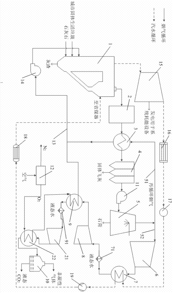
[0044] like figure 1 As shown, a garbage harmless treatment system, the treatment system includes a circulating fluidized bed boiler 1, a denitrification device 2, a gas-gas heat exchanger 3, a dust collector 4, a desulfurization device 5, a first A compressor 6, a first condenser 7, a first liquid water collector 71, a second compressor 8, a second condenser 9, a second liquid water collector 91, a third compressor 21, and a third condenser 22 and gas-liquid separator 10;

[0045] The denitrification device 2 communicates with the hot blast inlet of the gas-gas heat exchanger 3; the dust remover 4 communicates with the hot blast outlet of the gas-gas heat exchanger 3; A booster fan 11 is provided on the pipeline.

[0046] The outlet of the desulfurization device 5 is also in communication with the cold air inlet of the gas-gas heat exchanger 3; the output pipeline at the outlet of the desulfurization device 5 includes a first branch pipeline 52 and a second branch pipeline ...


PUM


Abstract

The invention relates to a harmless disposal system for refuse and a method for refuse disposal by the harmless disposal system. The refuse is subjected to combustion disposal by a circulating fluidized bed combustion technology, and O2 / CO2 mixed gas formed by mixing of high-concentration oxygen with recycled flue gas is adopted to substitute for air to participate in solid refuse combustion during refuse combustion. A relatively high-temperature combustion condition can be achieved in oxygen-enriched and oxygen-enriched combustion environments, and generation of dioxin and dioxin precursors is inhibited. After flue gas is subjected to denitration, dust removal and desulfurization, one part of the flue gas forms the recycled flue gas after being preheated by a gas-to-gas heat exchanger; after the other part of the flue gas is subjected to multi-stage compression and multi-stage cooling and water therein is recycled, high-purity liquid-state CO2 is formed to serves as chemical products or be used for oil well oil displacing or geological storage. The harmless disposal system adopting refuse combustion does not discharge gaseous pollutants any longer, so that the problem of secondary pollution caused by refuse combustion is solved thoroughly, and harmless disposal with near-zero emission of gaseous pollutants caused by refuse combustion is realized truly.

Description

technical field [0001] The invention relates to the technical field of garbage harmless treatment, in particular to a garbage harmless treatment system with near-zero discharge of pollutants after garbage combustion and a method for treating garbage using the system. Background technique [0002] In recent years, with the rapid development of the economy, the continuous expansion of the city and the rapid increase of the urban population, the amount of garbage generated is increasing day by day. Therefore, the reasonable disposal of garbage has become an environmental protection problem that needs to be solved urgently. The goal of waste disposal is volume reduction, resource utilization, energy utilization and harmlessness. At present, my country mainly uses three methods to deal with garbage, namely sanitary landfill, composting and incineration. Among them, sanitary landfill covers a large area. With the decreasing number of suitable landfill sites, sanitary landfill is...

Claims


Application Information

Patent Timeline
Patent Type & Authority Applications(China)
IPC IPC(8): F23G5/30F23G5/44F23J15/00F25J3/00
CPCF23G5/30F23G5/44F23G2203/50F23J3/00F23J15/006F23J2215/20F23J2215/301Y02E20/12Y02E20/34
Inventor 何伯述王超俊何頔段志鹏丁广超严林博裴晓辉宋泾舸李学政
Owner BEIJING JIAOTONG UNIV
Learn More