Method for growing carbon nano fibers on ceramic hollow microsphere surface in situ

A carbon nanofiber and in-situ growth technology, which is applied in the field of preparing carbon/ceramic composite hollow microspheres, can solve the problems of growing carbon nanotubes and carbon nanofibers, achieve uniform dispersion, avoid uneven dispersion, and low energy consumption Effect

Inactive Publication Date: 2015-06-24
SHANGHAI JIAO TONG UNIV +1
View PDF5 Cites 8 Cited by
  • Summary
  • Abstract
  • Description
  • Claims
  • Application Information

AI Technical Summary

Problems solved by technology

However, there have been no reports on the in situ growth of carbon nanot

Method used


Image

  • Method for growing carbon nano fibers on ceramic hollow microsphere surface in situ
  • Method for growing carbon nano fibers on ceramic hollow microsphere surface in situ
  • Method for growing carbon nano fibers on ceramic hollow microsphere surface in situ

Examples


Embodiment 1

[0037] Step 1: Add 8g of polyethersulfone to 90g of NMP, stir to dissolve, then add a mixture of 1.95g of stabilized zirconia ceramic powder and 0.05g of iron oxide powder, continue to stir and mix evenly, and age and degas to obtain a slurry.

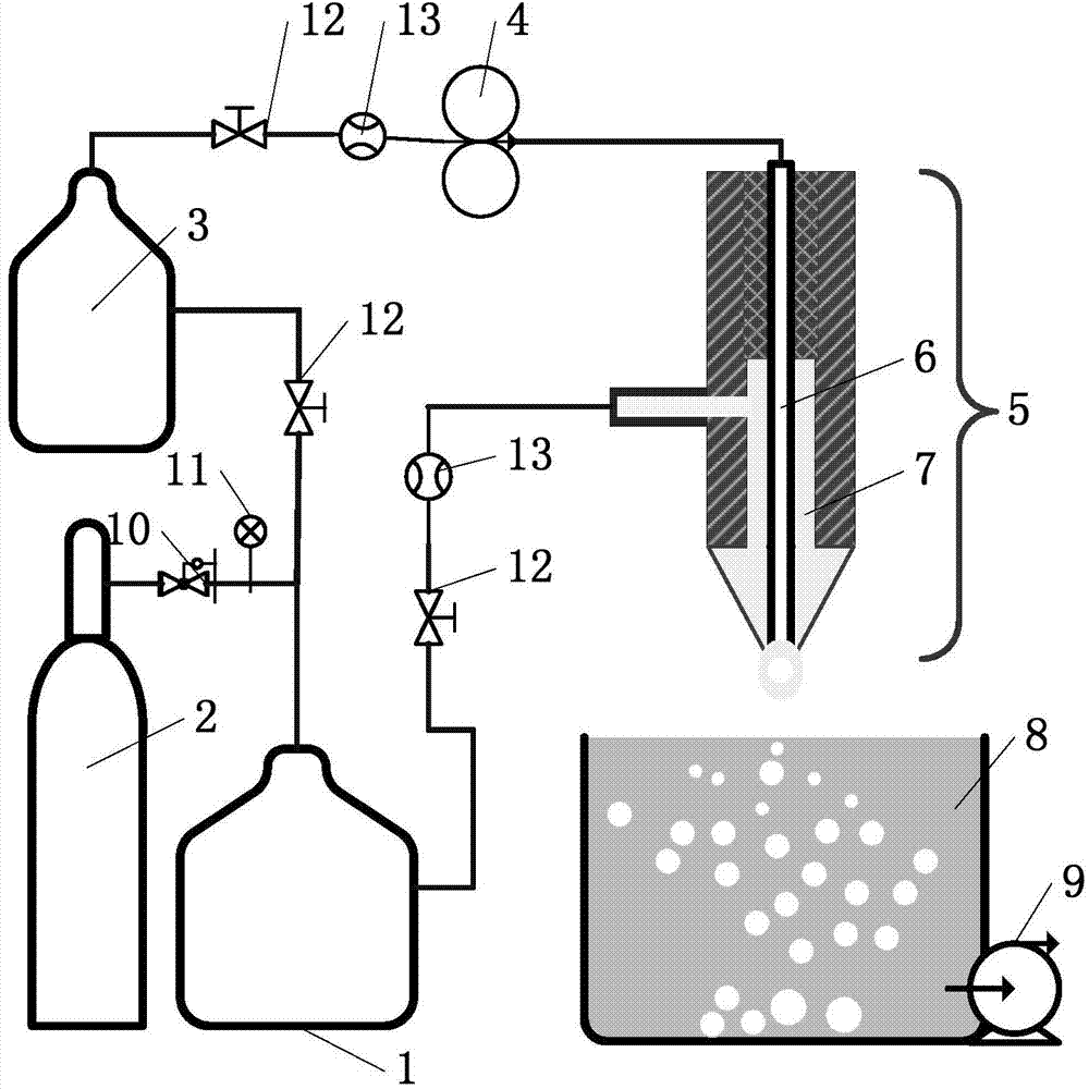
[0038] Step 2: Use deionized water as the non-solvent. The inner tube 6 of the coaxial nozzle has a diameter of 0.8 mm and the outer tube 7 of the coaxial nozzle has a diameter of 2.0 mm. The distance between the coaxial nozzle 5 and the non-solvent tank 8 is set to 10 mm. First open the compressed nitrogen drive pressure system: compressed nitrogen cylinder 2, pressure reducing valve 10, precision pressure gauge 11, screw valve 12, rotameter 13 to deliver the driving pressure within 0.1MP, by adjusting the non-solvent pipeline The rotary valve and the peristaltic pump speed (0.5 rev / min) make the non-solvent in the non-solvent tank 3 smoothly drop out in droplet shape. Then pour the slurry prepared in step 1 into the slurry tank 1, o...

Embodiment 2

[0042] Step 1: Add 28g of polyethersulfone to 60g of NMP, stir to dissolve, then add a mixture of 11.5g of silica powder and 0.5g of alumina nanopowder, continue to stir and mix evenly, and then age and degas to obtain a slurry.

[0043] Step 2: Use deionized water as a non-solvent. Choose a coaxial nozzle with a diameter of 0.5 mm in the inner tube 6 of the coaxial nozzle and a diameter of 1.2 mm in the outer tube 7 of the coaxial nozzle. Set the coaxial nozzle 5 and the non-solvent tank 8. The distance between them is 50mm. First open the compressed nitrogen drive pressure system: compressed nitrogen cylinder 2, pressure reducing valve 10, precision pressure gauge 11, screw valve 12, rotameter 13 to deliver the driving pressure within 0.1MP, by adjusting the non-solvent pipeline The rotary valve and the peristaltic pump speed (0.5 rev / min) make the non-solvent in the non-solvent tank 3 smoothly drop out in droplet shape. Then pour the slurry prepared in step 1 into the slur...

Embodiment 3

[0047] The method for growing carbon nanofibers in situ on the surface of ceramic hollow microspheres adopts the following steps:

[0048] (1) Precursor slurry configuration: ceramic powder and polymer form the solute, first add the polymer to the solvent N-methylpyrrolidone, stir and dissolve evenly, then add the ceramic powder, continue to stir evenly and then degas to obtain a suitable In situ synthesis of carbon nanofiber / ceramic hollow microsphere precursor slurry, the mass ratio of solute and solvent is 10:90, and the mass ratio of ceramic powder and polymer forming the solute is 20:80, wherein the ceramic powder Zirconia is a stable phase, and the polymer is cellulose acetate;

[0049] (2) Precursor preparation: the slurry is pushed into the outer tube of the nozzle of the coaxial microfluidic system by compressed gas in the liquid tank to form a continuous state fluid, and the pressure of the compressed air is 0.05MPa; The supply is controlled by the pump, the pressur...


PUM


Abstract

The invention relates to a method for growing carbon nano fibers on a ceramic hollow microsphere surface in situ, which comprises the steps of precursor slurry preparation, precursor preparation, and sintering carbonization. The method specifically comprises the following steps: synthesizing a carbon nano fiber/ceramic hollow microsphere precursor in situ by utilizing the principle of non-solvent induced phase separation; and carrying out room temperature drying and carbonization sintering treatment on the precursor to finally obtain the carbon nano fiber/ceramic composite material hollow microsphere. Compared with the prior art, the method does not need any metal catalyst or additional carbon source to grow the carbon nano fibers on the external surface and inside of the ceramic ball in situ, and has the advantages of uniform carbon nano fiber dispersion, favorable sphericity of ceramic balls, and controllable ball size and porosity, does not need to consume abundant energies and acid/alkali reagents. The technique is simple and can easily implement mass industrial production.

Description

technical field [0001] The invention relates to a method for preparing hollow microspheres of carbon / ceramic composite materials, in particular to a method for in-situ growth of carbon nanofibers on the surface of ceramic hollow microspheres. Background technique [0002] Hollow ceramic microspheres refer to a type of spherical shell material with a size ranging from several nanometers to several millimeters and a hollow structure inside. In recent years, ceramic / glass hollow microspheres have been widely used as filler materials, including lightweight fillers in polymers for various purposes; fillers in paint and coating materials; preparation of heat insulation and sound insulation dielectric materials; marine Develop and research buoyancy materials for deep water technology; composite materials of high-strength, non-deformable lightweight alloys and glass hollow microspheres, as well as filling materials for various insulation and heat insulation materials, etc. Carbon h...

Claims


Application Information

Patent Timeline
IPC IPC(8): C04B35/01C04B35/515C04B35/622
Inventor 郭芳威王国伟江志伟赵晓峰肖平
Owner SHANGHAI JIAO TONG UNIV
Why Eureka
Try Eureka