
Large-specific surface area graphite-phase carbonitride photocatalyst and application thereof in photocatalytic degradation reaction of TCP and photocatalysis reaction for hydrogen production
A technology of photocatalytic carbon nitride and large specific surface area, which is applied in the direction of physical/chemical process catalysts, hydrogen production, chemical instruments and methods, etc., and can solve problems such as unsatisfactory photocatalytic performance, small specific surface area, and complicated preparation , to achieve superior catalytic activity and stability, large specific surface area, and high catalytic activity
- Summary
- Abstract
- Description
- Claims
- Application Information
AI Technical Summary
Problems solved by technology
Method used
Image

Examples
Embodiment 1
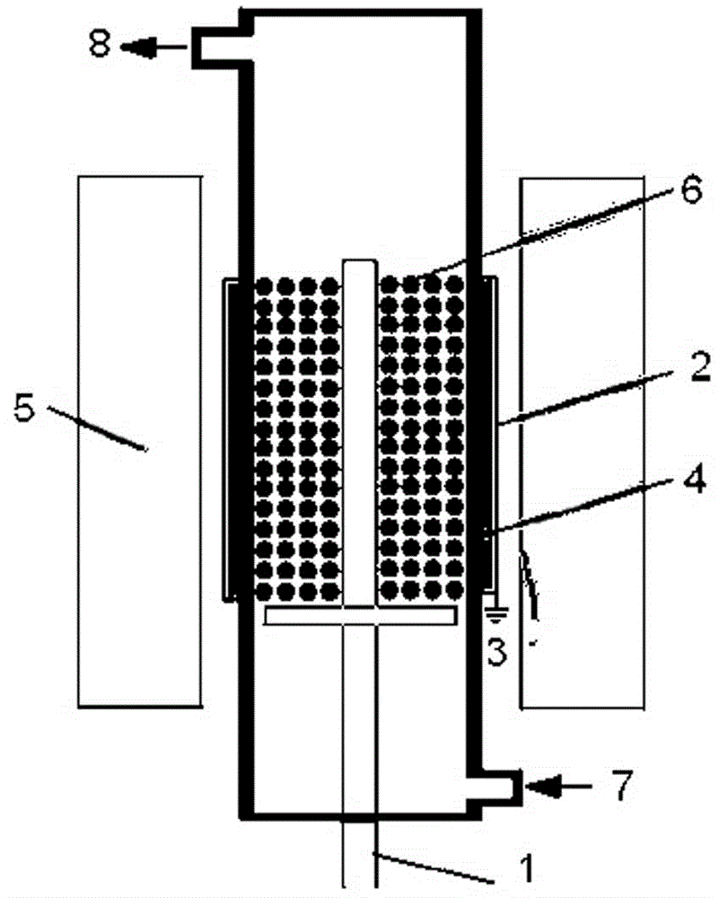
[0027] Using nitrogen as the discharge gas, the catalyst precursor melamine was discharged by using a dielectric barrier discharge plasma generator. The dielectric barrier discharge plasma generator consists of a quartz tube and two electrodes. A stainless steel wire with a diameter of 2.5 mm is used as a high-voltage electrode, which is installed at the axis of the quartz tube, and one end is connected to an AC power supply. The aluminum foil tightly wound outside the quartz tube is used as the ground electrode and connected to the ground. The structure diagram of the dielectric barrier discharge plasma generator is as follows: figure 1 Shown or use the existing commercially available plasma generator. see figure 1As shown, 1 is the high-voltage electrode; 2 is the ground electrode; 3 is the ground; 4 is the quartz tube; 5 is the heat insulation layer; 6 is the catalyst precursor bed; 7 is the gas inlet; 8 is the gas outlet. Put 0.5 g of melamine into the quartz tube, adj...
Embodiment 2
[0029] In Example 1, the catalyst precursor was changed to dicyandiamide, the input voltage was changed to 80 V, and other steps and conditions remained unchanged, a graphitic carbon nitride photocatalyst with a large specific surface area was obtained.
PUM
 Abstract
Description
Claims
Application Information