Gas, tar and activated carton co-production system

A technology of activated carbon and tar, applied in coke ovens, gas dust removal, petroleum industry and other directions, can solve the problems of unreachable chemical utilization, high water content in products, polluting the atmosphere, etc., to improve yield and recovery rate, novel and reasonable design , the effect of increasing production capacity

Active Publication Date: 2015-11-04
XIAN UNIV OF SCI & TECH
View PDF7 Cites 6 Cited by
  • Summary
  • Abstract
  • Description
  • Claims
  • Application Information

AI Technical Summary

Problems solved by technology

[0005] 1. Internal heating type dry distillation is adopted, and the furnace contains a large amount of air, so the generated gas has a low calorific value, contains low hydrogen, methane, and high nitrogen content, which cannot meet the best conditions for chemical utilization and can only be used as fuel
[0006] 2. The semi-coke is quenched by wet method, which consumes a part of the latent heat of semi-coke, and the product has a high water content, which affects the quality of semi-coke, limits the use of semi-coke, increases transportation costs, and consumes additional energy to dry it; in addition, the waste steam generated during the coke quenching process contains a large amount of toxic and harmful substances, which deteriorates the on-site operating environment and pollutes the atmosphere; and the large amount of phenol-containing wastewater generated by coke quenching is expensive for post-treatment
[0007] 3. Low recovery rate of tar

Method used


Image

  • Gas, tar and activated carton co-production system
  • Gas, tar and activated carton co-production system
  • Gas, tar and activated carton co-production system

Examples


Embodiment Construction

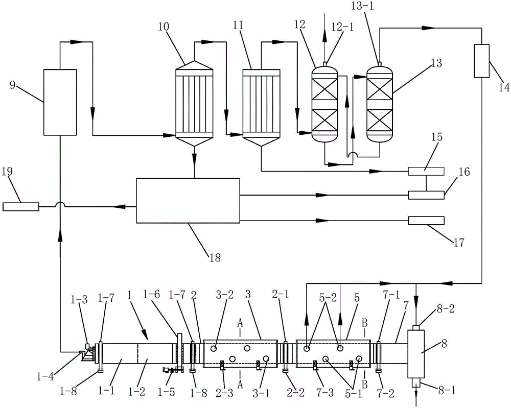
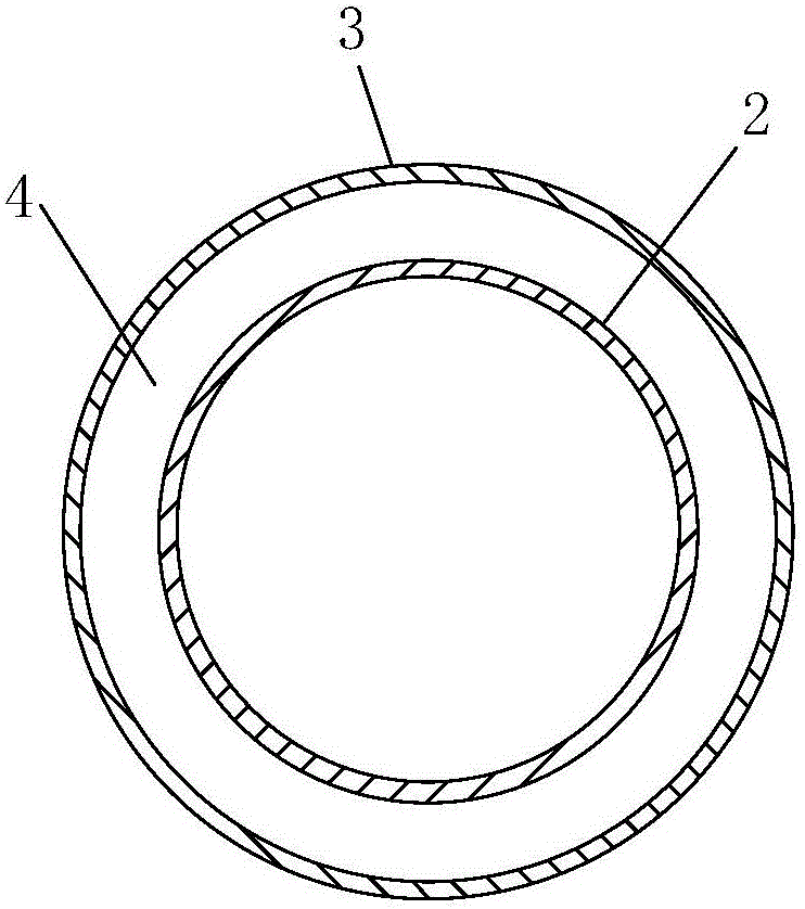
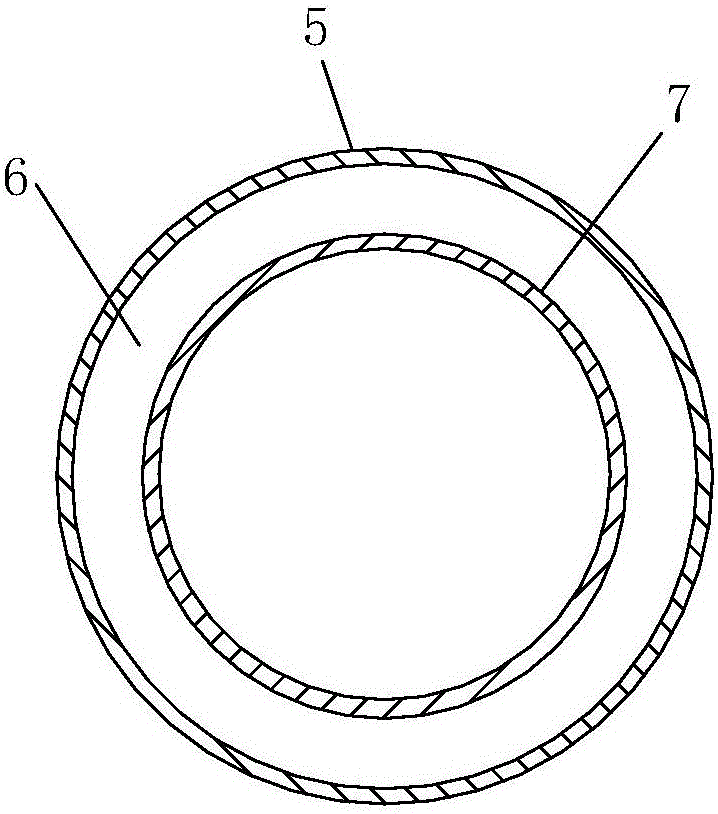
[0043] Such as figure 1 , figure 2 with image 3A co-production system of gas, tar and activated carbon is shown, including a pyrolysis furnace 1 for preheating and pyrolysis of coal, an activation furnace 2 for activating the semi-coke produced by pyrolysis, and a furnace for A cooling furnace 7 for cooling the activated carbon produced by activation, the pyrolysis furnace 1, activation furnace 2 and cooling furnace 7 are connected successively, and the pyrolysis furnace 1, activation furnace 2 and cooling furnace 7 are all rotary furnaces, so Described pyrolysis furnace 1 comprises preheating furnace body 1-1 and the pyrolysis furnace body 1-2 that is communicated with preheating furnace body 1-1, and described preheating furnace body 1-1 is away from pyrolysis furnace body 1-2 One end is provided with a coal inlet 1-3 and a pyrolysis gas outlet 1-4, and the outer side of the activation furnace 2 is provided with a thermal insulation jacket 3, and the activation furnace 2...


PUM

PropertyMeasurementUnit
particle diameteraaaaaaaaaa

Abstract

The invention discloses a gas, tar and activated carton co-production system. The system comprises a pyrolysis furnace, an activation furnace and a cooling furnace which are sequentially communicated. The pyrolysis furnace comprises a preheat furnace body and a pyrolysis furnace body, a coal inlet and a pyrolyzing gas outlet are formed in one end of the preheat furnace body, a heat-isolation jacket is disposed on the outer side of the activation furnace, and a heating chamber is formed between the activation furnace and the heat-isolation jacket; one end of the cooling furnace is connected with a discharge box, an activated carbon outlet and a cooling gas inlet are formed in the discharge box, a cooling jacket is arranged on the outer side of the cooling furnace, and a cooling chamber is formed between the cooling furnace and the cooling jacket; a cooling water inlet and a steam outlet are formed in the cooling jacket, and the steam outlet is communicated with the cooling gas inlet. Semicoke activated associated gas is used in the system to supply heat for pyrolysis, pyrolysis efficiency is improved, and meanwhile the content of nitrogen in pyrolysis gas is reduced. Mixed gas of carbon dioxide and water vapor can preheat the cooling furnace when passing through the cooling furnace and can prepare for being introduced in the activation furnace and serving as a gas activation agent, and activated carbon can be effectively cooled.

Description

technical field [0001] The invention belongs to the technical field of pyrolysis gas, tar and activated carbon production, and in particular relates to a combined production system of pyrolysis gas, tar and activated carbon. Background technique [0002] Activated carbon is a kind of loose and porous carbonaceous material with adsorption effect, which is widely used in chemical industry, medicine, environmental protection and other industries. Semi-coke, that is, semi-coke, is a solid substance with high fixed carbon content produced by a medium-low temperature dry distillation process. During the production of semi-coke, tar and coke oven gas are by-products. Semi-coke can be widely used in calcium carbide, iron alloys , Activated carbon preparation and urban residents clean coal and other production and living fields. Tar has a wide range of uses and can be used to produce clean fuel oil. It is also an important raw material for organic chemicals such as synthetic plastic...

Claims


Application Information

Patent Timeline
Patent Type & Authority Applications(China)
IPC IPC(8): C10B53/04C10B57/00C01B31/10C10K1/02C10K1/00C10K1/04C10K1/08B01D17/025C01B32/336
Inventor 周安宁贺新福杨志远宣兹润刘源任秀彬张亚刚
Owner XIAN UNIV OF SCI & TECH
Why Eureka
Try Eureka