Capacitive strain sensor and preparation method therefor

A technology of strain sensor and capacitance, which is applied in the direction of electric/magnetic solid deformation measurement and electromagnetic measurement device, etc., can solve the problems of unfavorable control of medium material quality, low strain and temperature, large dielectric loss, etc., and achieve accurate line width, The effect of high strain sensitivity and small temperature coefficient

Active Publication Date: 2015-11-04
UNIV OF ELECTRONIC SCI & TECH OF CHINA
View PDF8 Cites 17 Cited by
  • Summary
  • Abstract
  • Description
  • Claims
  • Application Information

AI Technical Summary

Problems solved by technology

K.I.Arshak et al. (K.I.Arshak, D.McDonagh, M.A.Durcan, Development of new capacitance strain sensors based on thick film polymer and cermet technologies, Sens.Actuators A: Phys.79(2000) 102-114) lead zirconate titanate ( PZT) and polyvinylidene fluoride (PVDF) have been prepared as dielectric materials for capacitive strain sensors, which have the following defects: the strain and temperature that can be tolerated are low, the maximum strain that can be tolerated is 350με, and the maximum operating temperature is

Method used


Image

  • Capacitive strain sensor and preparation method therefor
  • Capacitive strain sensor and preparation method therefor
  • Capacitive strain sensor and preparation method therefor

Examples


Embodiment 1

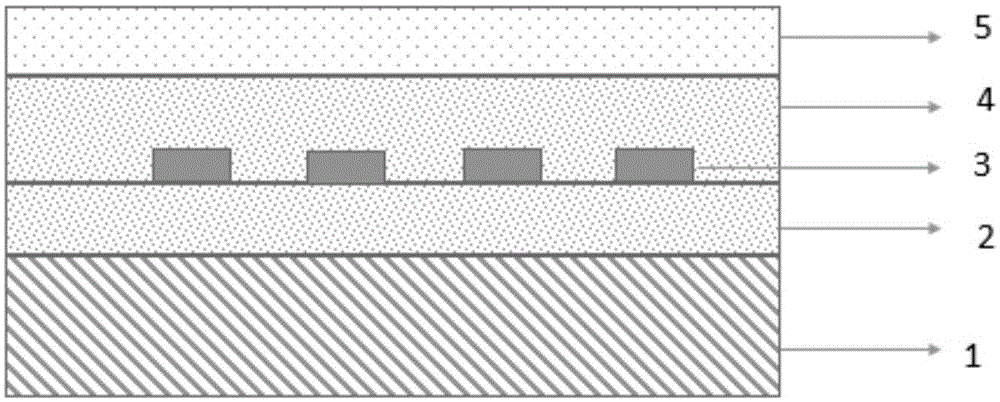
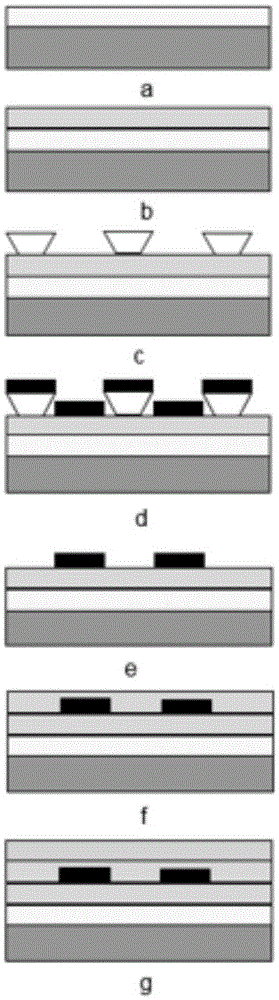
[0032] A preparation method of a capacitive strain sensor based on alumina ceramics, comprising the following steps

[0033] Step 1. Surface treatment of alumina substrate: use 1.25×1.25cm 99.9% alumina substrate as the substrate, successively use acetone, ethanol and deionized water to clean the substrate, and dry it with clean nitrogen after cleaning. ;

[0034] Step 2, depositing the first Ba on the alumina substrate 0.5 Sr 0.5 TiO 3 Dielectric film: put the alumina substrate cleaned in step 1 in a vacuum of 8.0×10 -4 Pa vacuum (back vacuum) environment, in Ba 0.5 Sr 0.5 TiO 3 Ceramic as the target material, argon gas with a purity of not less than 99.9% and 99.5% oxygen with a flow ratio of 4:1 as the reaction medium, at a temperature of 750°C, a power of 200W, and an air pressure of 2Pa, in alumina Deposit Ba with a thickness of 1 μm on the ceramic substrate 0.5 Sr 0.5 TiO 3 ceramic film;

[0035] Step 3, preparation of patterned PdCr interdigital electrodes: p...

Embodiment 2

[0051] A method for preparing a capacitive strain sensor based on an alloy, comprising the following steps:

[0052] Step 1. Surface treatment of the substrate: first, polish the surface of the alloy substrate, and the polished surface is a mirror surface; then ultrasonically clean it in acetone, ethanol and deionized water for 10 minutes respectively, and dry it with clean nitrogen after cleaning;

[0053] Step 2. Prepare a NiCrAlY transition layer on the surface of the substrate cleaned in step 1: In order to improve the service life of the strain sensor in harsh environments and make the film have good adhesion, prepare a layer of transition layer NiCrAlY on the surface of the alloy substrate; The clean alloy substrate is placed in a vacuum of 8.0×10 -4 Pa vacuum (back vacuum) environment, with Ni 67 Cr 22 al 10 Y alloy is used as the target material, and argon gas with a purity of 99.999% (volume percentage) is introduced as the sputtering medium. Under the conditions o...


PUM

PropertyMeasurementUnit
Thicknessaaaaaaaaaa
Thicknessaaaaaaaaaa
Thicknessaaaaaaaaaa

Abstract

The invention provides a capacitive strain sensor and a preparation method therefor, and belongs to the technical field of sensor design and production. The sensor is sequentially provided with a substrate, a first barium strontium titanate dielectric film layer, a PdCr electrode layer, a second barium strontium titanate dielectric film layer and an Al2O3 protection layer from the bottom to the top, wherein the PdCr electrode layer is in an interdigital electrode structure. The sensor employs an interdigital capacitive plane structure, takes barium strontium titanate (Ba0.5Sr0.5TiO3) as a dielectric material, takes PdCr as an electrode material, and achieves a purpose of stable operation under bigger strain (2500 mu*epsilon) and higher temperature (500 DEG C) employs a preparation technology combining magnetron sputtering coating with the photoetching technology.

Description

technical field [0001] The invention belongs to the technical field of sensor design and production, and in particular relates to a capacitive strain sensor and a preparation method thereof. Background technique [0002] Strain sensors play an important role in the study of mechanical properties and mechanical behavior of various components. At present, there are many types of strain sensors such as wire type, foil type, thin film type, metal, semiconductor, etc., most of which are based on the piezoresistive effect, that is, the resistance changes proportionally with the change of strain. Due to the high temperature requirements of the engine, nuclear power and other fields, the shortcomings of the application of resistive strain sensors at high temperatures are becoming more and more obvious, and the errors and reliability problems caused by high temperatures have become a huge challenge. The capacitive strain sensor is based on the change of the capacitance of the device...

Claims


Application Information

Patent Timeline
IPC IPC(8): G01B7/16
Inventor 蒋书文任帅张万里李言荣
Owner UNIV OF ELECTRONIC SCI & TECH OF CHINA
Why Eureka
Try Eureka