Manufacturing technology of multi-effect multi-stage vortex tube cold-hot dual-energy machine system

A manufacturing process and vortex tube technology, applied in the field of new energy utilization, can solve the problems of unstable or large-scale operation, lack of practicability, and difficulty in entering mainstream energy equipment for large-scale application.

Pending Publication Date: 2016-02-17
北京仲基应用技术研究院有限公司
View PDF15 Cites 10 Cited by
  • Summary
  • Abstract
  • Description
  • Claims
  • Application Information

AI Technical Summary

Problems solved by technology

The key point of the above-mentioned existing technical solutions is that the working medium is liquefied from low pressure to high pressure during the whole cycle process without using a return pump and compressor, which is difficult to realize, and the realization cost is higher than that of traditional refrigeration and heat pump equipment, and the process is cumbersome and complicated. Unable to run stably or on a large scale, lack of practicality
The prior art energy collection device (evaporator), the lack of the core device of the energy technology of this system is difficult to enter the mainstream energy equipment for large-scale application and other deficiencies.

Method used


Image

  • Manufacturing technology of multi-effect multi-stage vortex tube cold-hot dual-energy machine system
  • Manufacturing technology of multi-effect multi-stage vortex tube cold-hot dual-energy machine system
  • Manufacturing technology of multi-effect multi-stage vortex tube cold-hot dual-energy machine system

Examples


Embodiment ( 1

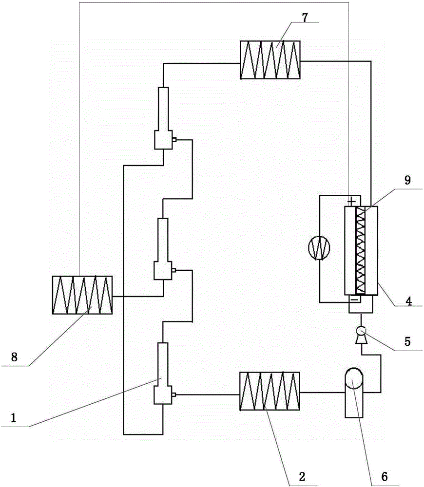
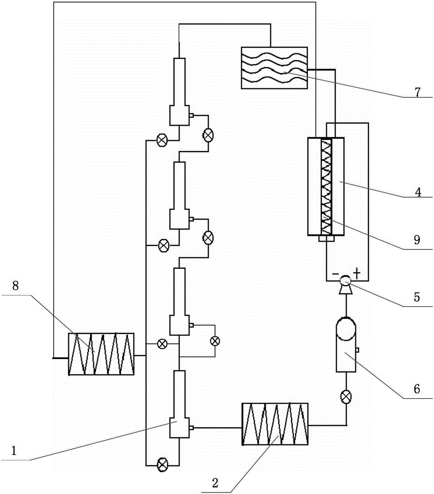
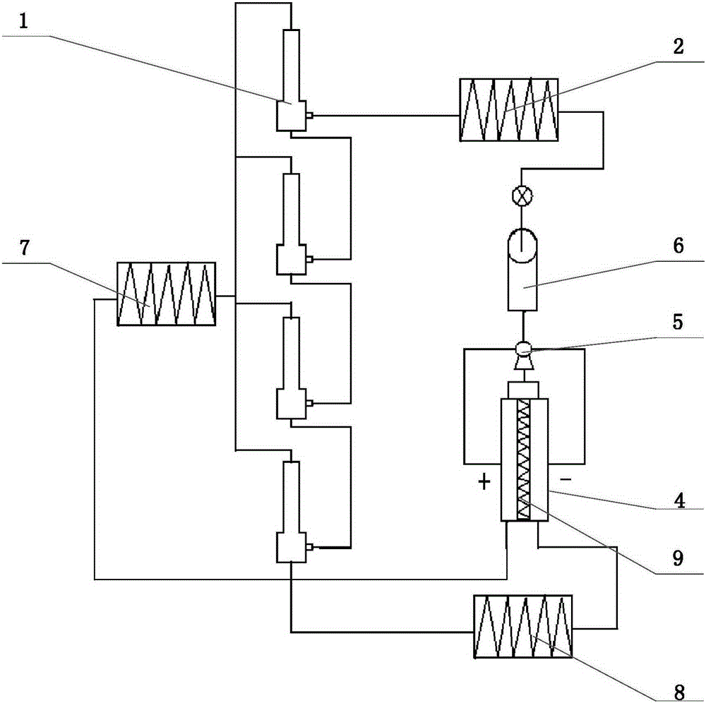
[0029] This embodiment is an embodiment in which heat energy is mainly used to provide a heat source. The vortex tube 1 is made of SUS304, and the intake flow is 40m 3 / min, 30m 3 / min, 20m 3 / min, the four vortex tubes are connected in multiple stages.

[0030] The basic energy-collecting evaporator 2 is made of aluminum alloy 7072 sunflower fin tubes. (Nominal pipe diameter DN × fin diameter × number of fins × tube wall thickness mm). The thermal conductivity of the material is 285W / m.k, the tube pressure is ≥3.8MPa, and the outer coating is selective (anodized) coating, the absorption rate of sunlight is ≥91%, and the infrared normal radiation emissivity is ≤10%.

[0031] The row spacing of fins is 200mm, and the energy-collecting area of ​​2 arrays of basic energy-collecting evaporators is 500 square meters. Select working fluid R134a, or R600, boiling point temperature: -26.1℃, critical temperature: 101.1℃, boiling point: -11.8℃, critical temperature: 134.98℃. The w...

Embodiment ( 2

[0039] The high temperature working fluid gas at 325°C discharged from the fourth-stage hot end enters the heat exchanger load. After heat exchange (multi-stage heat exchange is possible), the reflux working fluid gas can be set at 100-50°C and enters the thermoelectric power generation mixer. The power generation temperature difference is controlled between 30 and 100 °C. After the cold and heat neutralization is carried out by the semiconductor crystal thermoelectric power generation plate, the working fluid gas (below the critical temperature) of 15-30 °C flowing out of the mixed flow tube is pressurized to ≥18 MPa by the compressor, liquefied into the working fluid tank, and a cycle is completed. .

Embodiment ( 3

[0041] The low-temperature working medium gas at the cold end of the multi-stage vortex tube enters the air inlet of the next-stage vortex step by step, and finally achieves the cryogenic effect below -80 ℃, which meets the needs of quick freezing work. When cryogenic refrigeration, select the working fluid with ultra-low temperature boiling point, such as R170, R1150, R410A, etc. Since the boiling point of freon is generally ≤-40 °C, it will liquefy if it is lower than the boiling point. The liquid working medium flowing out of the solenoid valve at the outlet of the working medium tank enters the energy-collecting evaporator, and undergoes rapid phase change and vaporization through heat exchange with environmental energy (air energy, solar energy, etc.) The energy-carrying gas with the expansion and pressure increase of 3.0-5.0MPa rushes into the air inlet of the vortex tube, and is separated at a high speed by the vortex. The end outlet enters the air inlet of the second ...


PUM

PropertyMeasurementUnit
Thermal conductivityaaaaaaaaaa

Abstract

The invention belongs to the field of new energy utilization, and particularly relates to a manufacturing technology of a multi-effect multi-stage vortex tube cold-hot dual-energy machine system. The manufacturing technology is characterized in that a multi-stage vortex tube is provided; hot end outlets or cold end outlets of vortex tube parts are in series connection; a liquid working medium is subjected to phase change by a basic energy collection evaporator to form a gas phase energy carrying working medium; the gas phase energy carrying working medium enters a gas inlet tube of the first-stage vortex tube part; the cold end outlets of the vortex tube parts are connected with a cold energy heat exchanger; the hot end outlets are connected with a hot energy heat exchanger; an outlet of the cold energy heat exchanger and an outlet of the hot energy heat exchanger lead to a cold inlet and a hot inlet of a temperature difference power generation flow mixer respectively and correspondingly; an outlet of the temperature difference power generation flow mixer is connected with a reflux pump; the reflux pump is connected with a working medium tank; and the working medium tank is connected with the basic energy collection evaporator. With the combination of a temperature difference power generation technology, superhigh energy efficiency ratio hot-cold dual-energy can be produced stably by collecting natural energy such as air energy, solar power and seawater energy, and can be widely applied in power generation energy sources for building air conditioning, seawater desalination, and industrial and agricultural production.

Description

technical field [0001] The invention relates to a manufacturing process of a multi-effect multi-stage vortex tube cooling and heating dual-energy machine system, which belongs to the field of new energy utilization. Background technique [0002] The traditional vortex tube equipment mainly uses the vortex (cold and heat separation) effect of the vortex tube, uses compressed air, and the air compressor equipment as the energy power source to generate cold or hot air at -45 to +130°C to meet the needs of cold and hot energy. It is used in some special environments that are not convenient for the use of traditional air conditioners. Because compressed air is a one-time discharge, simple and environmentally friendly, energy efficiency ratio (EER, COP) is lower, and the cost is higher than traditional mainstream air conditioners, it is not suitable for mainstream and large-scale promotion and use. [0003] In the prior art, there is a method of circulating power generation witho...

Claims


Application Information

Patent Timeline
IPC IPC(8): F25B9/04F25B29/00F25B39/00
CPCF25B9/04F25B29/003F25B39/00
Inventor 许刚窦小琳陈海帆赵军平许亮刘昭勇
Owner 北京仲基应用技术研究院有限公司
Why Eureka
Try Eureka