Differential-output infrared detector unit structure and manufacturing method

An infrared detector and unit structure technology, applied in microstructure technology, microstructure devices, electrical radiation detectors, etc. It can improve the sensitivity, enhance the mechanical strength and stability, and improve the infrared absorption effect.

Active Publication Date: 2016-03-23
SHANGHAI INTEGRATED CIRCUIT RES & DEV CENT
View PDF6 Cites 19 Cited by
  • Summary
  • Abstract
  • Description
  • Claims
  • Application Information

AI Technical Summary

Problems solved by technology

[0006] The existing MEMS infrared detectors use amorphous silicon or alum with negative temperature coefficient as the thermistor to absorb infrared rays. The temperature coefficient of resistance of amorphous silicon is about 2-3%, and that of alum is relatively low. Higher, about 3-4%; after process integration, the temperature coefficient of resistance of amorphous silicon or alumina will further deteriorate, resulting in a decrease in the sensitivity of MEMS infrared detectors
[0007] In the prior art, in order to solve the problem that the temperature coefficient of resistance of amorphous silicon or aluminum oxide becomes worse after process integration, it is usually necessary to increase the area of ​​the pixel, that is, increase the area of ​​the thermistor, to keep the MEMS infrared detector without loss of sensitivity
However, this method is not in line with the miniaturization and portable development direction of MEMS infrared detectors.

Method used


Image

  • Differential-output infrared detector unit structure and manufacturing method
  • Differential-output infrared detector unit structure and manufacturing method
  • Differential-output infrared detector unit structure and manufacturing method

Examples


Embodiment Construction

[0045] The specific embodiment of the present invention will be further described in detail below in conjunction with the accompanying drawings.

[0046] It should be noted that, in the following specific embodiments, when describing the embodiments of the present invention in detail, in order to clearly show the structure of the present invention for the convenience of description, the structures in the drawings are not drawn according to the general scale, and are drawn Partial magnification, deformation and simplification are included, therefore, it should be avoided to be interpreted as a limitation of the present invention.

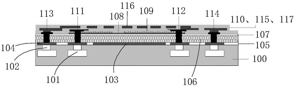
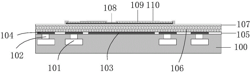
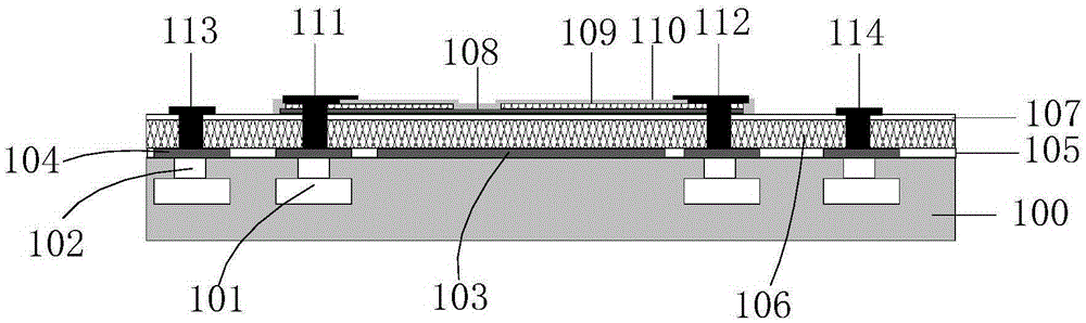
[0047] In the following specific embodiments of the present invention, please refer to figure 1 , figure 1 It is a structural schematic diagram of an infrared detector unit with differential output in a preferred embodiment of the present invention. Such as figure 1As shown, a differential output infrared detector unit structure of the present inv...


PUM


Abstract

The invention discloses a differential-output infrared detector unit structure and a manufacturing method. According to the differential-output infrared detector unit structure and the manufacturing method, based on the negative sensitive material layer structure of an existing pixel which has a negative temperature coefficient, a positive sensitive material layer with a positive temperature coefficient is additionally adopted, so that a double-layer composite structure of an infrared pixel can be formed, and therefore, with the area of the pixel not increased, the infrared absorption effect of an MEMS infrared detector can be improved, and the sensitivity of the MEMS infrared detector can be the improved; the negative sensitive material layer and the positive sensitive material layer are respectively provided with two metal supporting column structures; a micro bridge structure is fixed to the metal supporting column structures through an insulating isolation layer, and therefore, the mechanical strength and stability of the micro bridge structure can be effectively enhanced; and a peripheral readout circuit is provided with a differential sensitive amplifier circuit, so that noises generated by some parasitic effects in the infrared detector unit structures can be eliminated, and therefore, high-sensitivity and low-noise MEMS infrared detectors can be obtained.

Description

technical field [0001] The invention relates to the technical field of micro-electro-mechanical systems (MEMS), and more particularly relates to a structure and a manufacturing method of an infrared detector unit with differential output compatible with a CMOS process. Background technique [0002] Micro-electro-mechanical system (MEMS) technology has many advantages such as small, intelligent, executable, integrated, good process compatibility, and low cost, so it has begun to be widely used in many fields including the field of infrared detection technology. [0003] Infrared detector is a MEMS product widely used in the field of infrared detection technology. It generally uses a MEMS microbridge structure integrated on a CMOS circuit, and uses a thermistor (usually amorphous silicon or aluminum oxide with a negative temperature coefficient) Absorbs infrared rays, and converts the changing signal into electrical signal amplification and output through the circuit, so as to...

Claims


Application Information

Patent Timeline
Patent Type & Authority Applications(China)
IPC IPC(8): G01J5/10B81C1/00B81B7/02
CPCB81B7/02B81C1/00G01J5/10
Inventor 康晓旭
Owner SHANGHAI INTEGRATED CIRCUIT RES & DEV CENT
Why Eureka
Try Eureka