
MTP (methanol to propylene) device and novel separation process thereof

A process and separation tank technology, applied in the MTP device and its new separation process field, can solve the problems of system equipment, pipeline corrosion, pipeline corrosion, large investment, etc., to save equipment investment and operating costs, facilitate comprehensive utilization, and improve economic efficiency benefit effect

Active Publication Date: 2016-04-20
BC P INC CHINA NAT PETROLEUM CORP +1
View PDF8 Cites 19 Cited by
  • Summary
  • Abstract
  • Description
  • Claims
  • Application Information

AI Technical Summary

Problems solved by technology

In addition to the complicated refrigeration compressor system, a cold box with a precise structure is also required, which makes the cryogenic separation process complicated and requires a large investment
The high temperature at the top of the demethanizer leads to entrainment of by-product ethylene in the fuel gas
The alkali washing tower is installed after the deethanizer tower, resulting in serious corrosion of the front system equipment and pipelines
In addition, the purity of liquefied gas products is not high and contains impurities such as DME, which is not conducive to the deep processing of liquefied gas
The above unfavorable factors limit the development of MTP technology
[0006] Chinese patent CN102304009A adopts the post-separation process of the conventional ethylene cracking unit, and sets the alkali washing tower after the second stage of compression, which solves the problem of corrosion of the pre-system equipment and pipelines, but also needs to set up a complex cryogenic system

Method used


Image

  • MTP (methanol to propylene) device and novel separation process thereof
  • MTP (methanol to propylene) device and novel separation process thereof

Examples


Embodiment Construction

[0037] The following will clearly and completely describe the technical solutions in the embodiments of the present invention with reference to the accompanying drawings in the embodiments of the present invention. Obviously, the described embodiments are only some of the embodiments of the present invention, not all of them. Based on the embodiments of the present invention, all other embodiments obtained by persons of ordinary skill in the art without making creative efforts belong to the protection scope of the present invention.

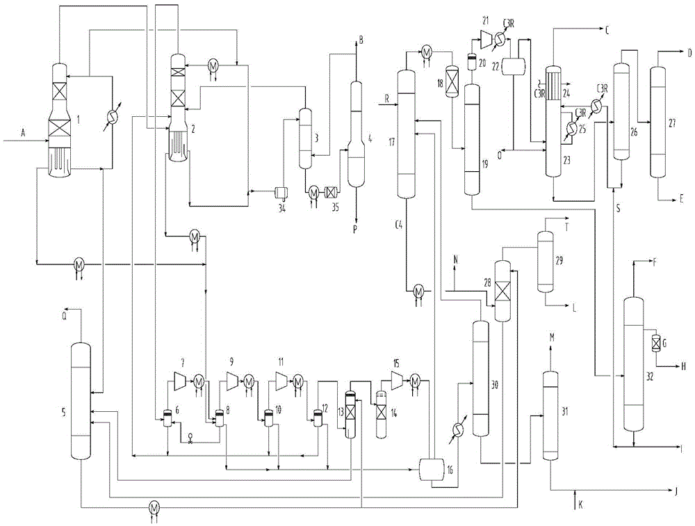
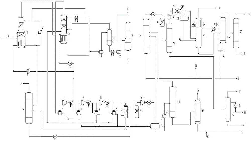
[0038] figure 1 Schematic diagram of the separation process for propane as the absorbent, setting the middle section of the oil absorption tower for reflux and C4 purified MTP reaction gas; the following combination figure 1 Embodiment 1 of the present invention will be described in detail.

[0039] Such as figure 1 As shown, the reaction gas from the MTP reactor is about 190°C, first enters the pre-quench tower and washes it with pre-quench wa...


PUM


Abstract

The invention relates to an MTP (methanol to propylene) separation device and a novel separation process adopted by the MTP device. The novel separation process comprises the steps that quenched reaction gas is pressurized by a compressor and undergoes washing and alkali wash treatment on a third compression section, a gas phase at the outlet of a fourth compression section goes to a depropanizer and a liquid phase goes to a debutanizer, water phases of separating tanks among the sections of the compressor return to a quench tower, and a hydrocarbon phase is sent to a separating tank at the outlet of the fourth compression section after being pressurized; the materials ejected from the debutanizer go to the depropanizer and the materials discharged from tower reactors enter a dehexanizer; a deethanizer compressor is arranged between a deethanizer and an oil absorption tower, the oil absorption tower adopts recycle propane or C4 as an absorbing solvent, fuel gas excluding C2 is obtained at the tower tops, the materials discharged from the tower reactors go to a stripping tower to recover the propane or C4 solvent, and the materials ejected from the stripping tower go to an ethylene rectification tower, thus obtaining the byproduct ethylene. The novel separation process has the effects that the process flow can be effectively optimized; the energy consumption of systems, the pipeline corrosion and the cost of investment can be effectively reduced.

Description

technical field [0001] The invention relates to the fields of coal chemical industry, natural gas chemical industry and the like, in particular to an MTP device and a novel separation process thereof. Background technique [0002] Propylene is one of the most important basic organic raw materials, mainly used in the production of chemical products such as polypropylene, acrylonitrile, propylene oxide, cumene, butanol and octanol. With the sustained and rapid development of my country's economy, my country's demand for propylene and its downstream products has shown a substantial upward trend, and the problem of propylene shortage has become increasingly prominent. At present, propylene mainly comes from steam cracking ethylene units and catalytic cracking units. In the case of increasingly tight oil supply, people have developed a process for producing propylene from oxides, especially methanol. [0003] MTP methanol to propylene process refers to the chemical process tech...

Claims


Application Information

Patent Timeline
Patent Type & Authority Applications(China)
IPC IPC(8): C07C1/20C07C7/00C07C7/04C07C7/11C07C11/06C07C11/04C07C9/06C10G53/00
CPCC07C1/20C07C7/005C07C7/04C07C7/11C10G53/00C10G2300/1037C10G2400/02C10G2400/26C07C11/06C07C11/04C07C9/06Y02P30/20Y02P30/40
Inventor 张霄航王勇李玉鑫曹新波郭克伦路聿轩曹媛维姜南
Owner BC P INC CHINA NAT PETROLEUM CORP
Learn More