Rubber wastewater treatment process

A technology of rubber wastewater and treatment process, applied in water/sewage treatment, biological water/sewage treatment, neutralized water/sewage treatment, etc. The effect of improving biodegradability and reducing processing load

Active Publication Date: 2016-08-17
云南今业生态建设集团有限公司
View PDF5 Cites 1 Cited by
  • Summary
  • Abstract
  • Description
  • Claims
  • Application Information

AI Technical Summary

Problems solved by technology

[0004] ①The advantage of the natural aeration method of anaerobic-oxidation ponds is that the structure is simple, but it occupies a large area and takes a long time to process (only 20~25 days for a single oxidation pond), and the anaerobic section produces stench
Although the anaerobic-oxidation pond natural aeration method omits the oxidation pond and occupies a small area, the anaerobic section increases the follow-up NH3-N conformation (whether anaerobic fermentation or other processes such as UASB), and also produces foul odor and takes a long time to process
[0005] ②Practice aeration in the aerobic section. Although the treatment effect is high, it needs to bear the increased NH3-N load in the anaerobic section, and lacks subsequent denitrification links such as the subsequent anoxic denitrification section, resulting in poor NH3-N treatment effect.
[0006] ③Oxidation pond-activated sludge mechanical forced aeration method covers a large area, takes a long time without treatment, and has high continuous aeration efficiency but lacks subsequent denitrification links, resulting in poor NH3-N treatment effect
[0007] ④ Oxidation pond natural aeration oxidation method, covers a large area, and there will be stench when the aeration is not sufficient
The high-efficiency algae pool (HRAP) and intermittent sand filter (ISF) built on this basis, although HRAP can reduce the content of organic matter, but the growth regulation of algae and the intermittent fully automatic operation of ISF greatly increase the processing difficulty and The disadvantages of investment cost and large footprint have not been overcome

Method used


Image

  • Rubber wastewater treatment process

Examples


Embodiment 1

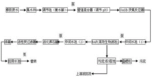
[0038] Step A pretreatment: the rubber wastewater flows into the water collection well after the large particles of impurities are removed by the artificial grid, and the dosing system and its pH meter are installed in front of the water collection well, and the water collection well is equipped with a submersible sewage pump; The pool is equipped with a submersible mixer to mix the water quality and remove some organic matter under the action of facultative organic matter;

[0039] Step B removes most of the organic matter and total phosphorus: the wastewater treated in step A is pumped into the UASB tank, and after anaerobic digestion, the UASB tank is composed of a sludge reaction zone, a gas-liquid-solid three-phase separator (including a sedimentation zone) The air chamber consists of three parts;

[0040] Step C to remove COD and BOD: the wastewater treated in step B flows into the intermediate pool (1) by itself, stays for 1.3 hours, and then lifts it to the BAF reactio...


PUM


Abstract

The invention discloses a rubber wastewater treatment process. Large-particle impurities in rubber wastewater are removed through an artificial grille, then the rubber wastewater automatically flows into a water-collecting well, water quality mixture is performed through a regulating hydrolysis tank, parts of organic matter are removed under the effect of facultative anaerobic organic matter, then most of organic matter and total phosphorus are removed through a UASB tank, COD, BOD and other pollutants are removed through a BAF reaction tank, CODcr, NH3-N, SS and total phosphorus in the water are removed through an activated zeolite filter and a biological activated carbon filter, and then the wastewater enters a recovery pool and is lifted to a pipe network system through a pump. The water for backflushing of a BAF, the activated zeolite filter and the biological activated carbon filter enters a sludge concentration pool, a part of supernatant is subjected to reflux through the pump and then enters the regulating hydrolysis tank, and dewatered sludge can serve as a fertilizer used in farmland or rubber forests. The process is feasible in operation, and treated wastewater conforms to the national discharge standards.

Description

technical field [0001] The invention belongs to the field of waste water treatment, and in particular relates to a treatment process for rubber waste water. Background technique [0002] The two main finished products of natural rubber are raw natural rubber and concentrated latex. During the processing of natural raw rubber, the whey that flows out naturally from the coagulation of fresh latex and the whey that comes out of the clot through thinning and creping are the main sources of wastewater in the production process, and there is also part of the wastewater generated by the cleaning of the granulation workshop. This wastewater is high-concentration organic wastewater with high acidity, high CODcr content, high suspended solids and bacteria. If it is not treated and discharged directly, it will pollute the surrounding environment, affect the water quality of the river, and destroy the ecological balance. Therefore, it is important to manage the wastewater from the rubbe...

Claims


Application Information

Patent Timeline
Patent Type & Authority Applications(China)
IPC IPC(8): C02F9/14C02F101/20C02F101/22C02F101/34
CPCC02F1/00C02F1/001C02F1/66C02F3/02C02F3/2846C02F3/30C02F9/00C02F2003/003C02F2101/20C02F2101/203C02F2101/22C02F2101/345
Inventor 邓辅商邓辅唐曾郴林
Owner 云南今业生态建设集团有限公司
Why Eureka
Try Eureka