

Preparation technology of molybdenum-niobium alloy sputtering target material
A molybdenum-niobium alloy, sputtering target technology, applied in metal material coating technology, sputtering coating, metal processing equipment and other directions, can solve the problems of low sintered blank density, low target yield, affecting thermal processing, etc. , to achieve the effect of simple preparation process, less dosage and lower surface energy
- Summary
- Abstract
- Description
- Claims
- Application Information
AI Technical Summary
Problems solved by technology
Method used
Image

Examples
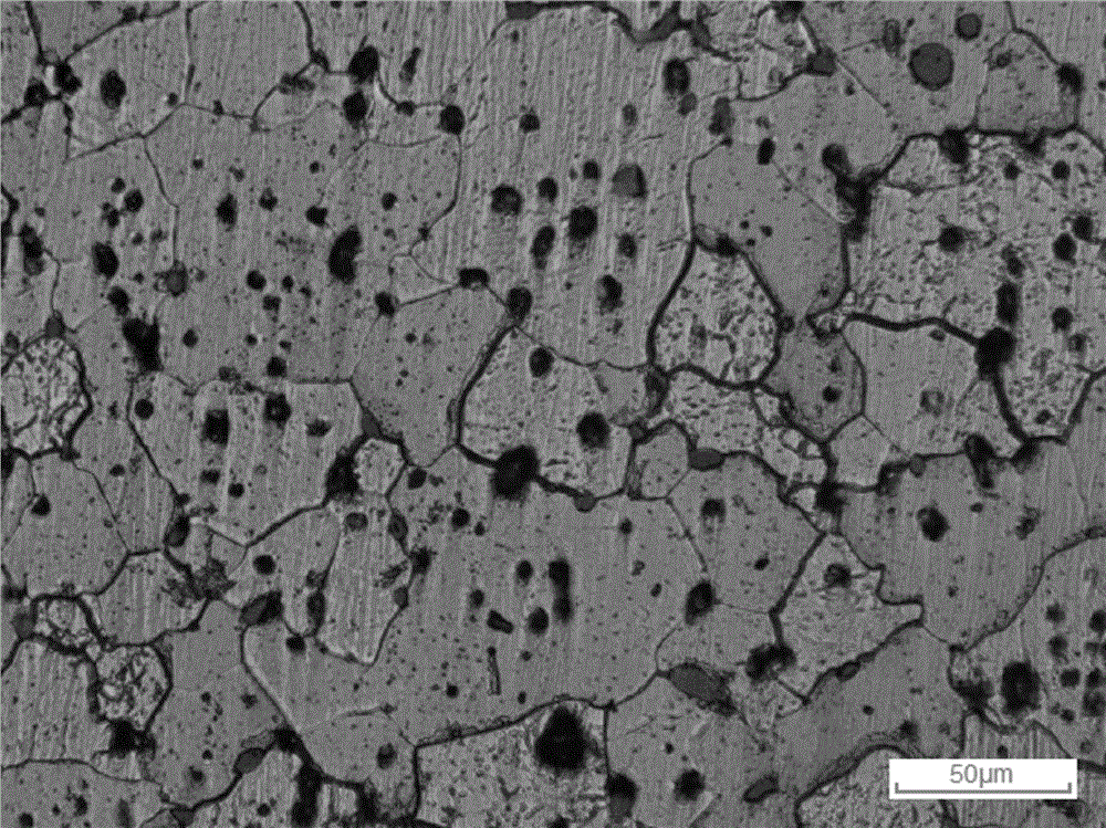
Embodiment 1
[0030] A preparation process of a molybdenum-niobium alloy sputtering target, comprising the following steps:
[0031] (1) Put molybdenum powder and niobium powder (purity ≥99.95%, particle size 20μm and 35μm respectively) into the ball mill at a weight ratio of 6:1, and then add palmitic acid and zirconia grinding balls (grain diameter 2mm), ball milling was carried out under the protection of argon, the ball milling time was 80min, the ball milling speed was 1000r / min, sieved, and separated to obtain a molybdenum-niobium alloy composite powder with a particle size of 9 μm;
[0032] The weights of the palmitic acid and zirconia grinding balls are respectively 0.02 times and 8 times of the total weight of molybdenum powder and niobium powder;
[0033] (2) Perform cold isostatic pressing of the molybdenum-niobium alloy composite powder in step (1), the pressure of cold isostatic pressing is 200 MPa, and the holding time is 5 minutes to obtain a pressed blank;
[0034] (3) The ...
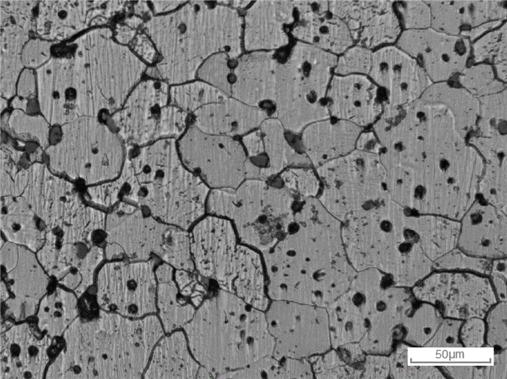
Embodiment 2
[0037] A preparation process of a molybdenum-niobium alloy sputtering target, comprising the following steps:
[0038] (1) Put molybdenum powder and niobium powder (purity ≥ 99.95%, particle size 15 μm and 30 μm respectively) into the ball mill at a weight ratio of 7:1, and then add zinc stearate and zirconia grinding balls (particle size 3mm), ball milling is carried out under the protection of argon, the ball milling time is 60min, the ball milling speed is 1200r / min, sieved, separated to obtain molybdenum-niobium alloy composite powder with a particle size of 10μm;
[0039] The weights of the zinc stearate and zirconia grinding balls are respectively 0.01 times and 5 times the total weight of molybdenum powder and niobium powder;
[0040] (2) Perform cold isostatic pressing of the molybdenum-niobium alloy composite powder in step (1), the pressure of cold isostatic pressing is 150 MPa, and the holding time is 10 minutes to obtain a pressed blank;
[0041] (3) The pressed b...
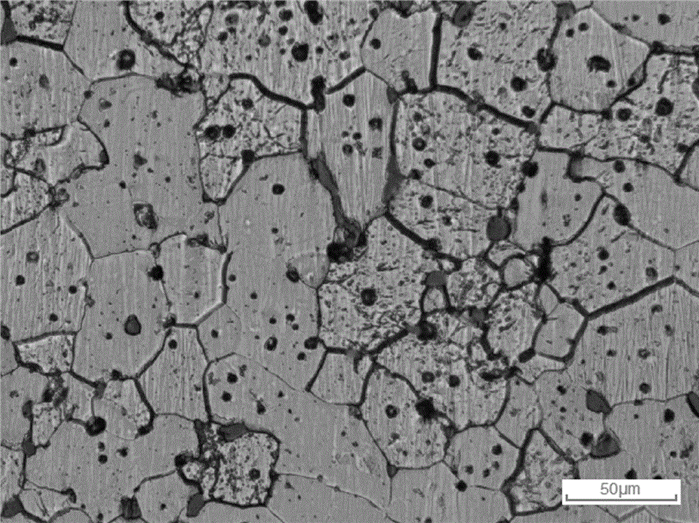
Embodiment 3
[0044] A preparation process of a molybdenum-niobium alloy sputtering target, comprising the following steps:
[0045] (1) Put molybdenum powder and niobium powder (purity ≥ 99.95%, particle size 25 μm and 40 μm respectively) into the ball mill at a weight ratio of 8:1, and then add stearic acid and zirconia grinding balls ( Particle size 1mm), ball milling is carried out under the protection of argon, the ball milling time is 100min, the ball milling speed is 1000r / min, sieved, and separated to obtain molybdenum-niobium alloy composite powder with a particle size of 6 μm;
[0046] The weight of described stearic acid, zirconia grinding ball is respectively 0.03 times, 10 times of molybdenum powder and niobium powder gross weight;
[0047] (2) Vacuumize the molybdenum-niobium alloy composite powder in step (1), and then perform cold isostatic pressing. The pressure of cold isostatic pressing is 180 MPa, and the holding time is 7 minutes to obtain a pressed blank;
[0048] (3)...
PUM
| Property | Measurement | Unit |
|---|---|---|
| particle diameter | aaaaa | aaaaa |
| density | aaaaa | aaaaa |
| particle size | aaaaa | aaaaa |
Abstract
Description
Claims
Application Information