
Bipolar membrane electro-catalysis treatment device

A bipolar membrane and treatment device technology, applied in electrochemical water/sewage treatment, water/sewage treatment, chemical/physical process, etc., can solve the problems of large current, large energy consumption, and shrinkage.

Pending Publication Date: 2016-12-21
江苏金点环保科技有限公司
View PDF6 Cites 0 Cited by
  • Summary
  • Abstract
  • Description
  • Claims
  • Application Information

AI Technical Summary

Problems solved by technology

Biological treatment is used, high concentration of salt substances can inhibit microorganisms, and physical and chemical treatment requires large investment and high operating costs, and it is difficult to achieve the expected purification effect
[0004] The existing electrocatalytic devices for treating high-concentration and high-salt organic wastewater have the following disadvantages: (1) Due to the high salinity, the conductivity of the wastewater is good, the current is large, and the energy consumption for treatment is too large; (2) The influent is mixed with the inflow , causing the residence time to be greatly reduced compared with the design, which affects the treatment effect

Method used


Image

  • Bipolar membrane electro-catalysis treatment device
  • Bipolar membrane electro-catalysis treatment device
  • Bipolar membrane electro-catalysis treatment device

Examples


Embodiment 1

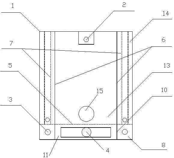
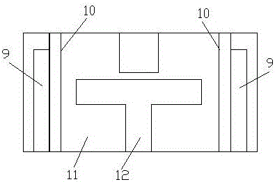
[0035] Embodiment 1: A bipolar membrane electrocatalytic treatment device, including a housing (1), a water outlet weir (2) located above the housing (1), a water inlet (3) located below the housing (1), and an air inlet (4), the bottom of the housing (1) is provided with a No. 1 isolation plate (5) and a No. 2 isolation plate (6) on both sides. An ion-selective membrane (7) is provided between them, and the innermost side of the housing (1) is an electrocatalytic plate (14); the bottom No. 1 separator (5) inside the housing (1) is connected to the (1) There is a water distribution chamber (8) and an air distribution chamber (11) between the bottom, and the area above the No. 1 isolation plate (5) is the reaction area (13). The ion-selective membrane (7) is a monolithic ion-selective membrane, and the polarity of the monolithic ion-selective membranes on both sides inside the casing (1) is opposite, and is consistent with the polarity of the power supply connected to the elect...

Embodiment 2

[0037] Embodiment 2: the carbon electrocatalyst catalyst comprises the following preparation steps:

[0038] (1) Raw material configuration:

[0039] Toner 240kg;

[0040] Nickel powder 20kg;

[0041] Iron powder 32 kg;

[0042] Manganese powder 60 kg;

[0043] Aluminum powder 24 kg;

[0044] Magnesium powder 2kg;

[0045] Titanium powder 2kg;

[0046] Phosphorus pentoxide 2kg;

[0047] Silica fume 16kg;

[0048] Calcium oxide 2kg;

[0049] Weigh the raw materials in proportion and put them into the mixer for wet mixing;

[0050] (2) Grind the raw materials to control the final particle size to ≤3um. The raw material powder is mixed with methane-nitrogen ratio of 2:1 and heated to 170°C in the absence of air. Weigh 200kg of alcohol and 20kg of high-temperature modified asphalt, add high-temperature modified asphalt to the alcohol, and add 0.4kg of anti-settling agent polyglycol ether and 0.4kg of carbonization accelerator carbodiimide, stir evenly, and make a mixed ...


PUM

PropertyMeasurementUnit
Diameteraaaaaaaaaa
Diameteraaaaaaaaaa
Lengthaaaaaaaaaa

Abstract

The invention provides a bipolar membrane electro-catalysis treatment device. The bipolar membrane electro-catalysis treatment device comprises a shell, an effluent weir (2) located on the upper portion of the shell (1), water inlets (3) located in the lower portion of the shell (1), and an air inlet (4). A first isolation plate (5) is arranged at the bottom end in the shell (1), second isolation plates (6) are arranged on the two sides of the shell (1), ionic selection membranes (7) are arranged between the second isolation plates (6) and the shell (1) respectively, and an electro-catalysis polar plate (14) is arranged on the edge in the shell (1). A water distribution chamber (8) and an air distribution chamber (11) are arranged between the first isolation plate (5) at the bottom end in the shell (1) and the bottom of the shell (1), and the region above the first isolation plate (5) serves as a reaction region (13). Based on the electrochemical and ionic selection transmission principle, wastewater is treated through electro-catalysis and the ionic membranes, a special carbon material is used as an electro-catalyst for electro-catalysis to remove organic matter, and the purposes of organic matter degradation, desalting and acid and alkali recovery of the wastewater are achieved.

Description

technical field [0001] The invention relates to the technical field of sewage treatment, in particular to a device for treating high-salt and high-concentration organic waste water by using a bipolar selective permeable membrane and the principle of electrocatalysis. Background technique [0002] In recent years, with the development of industrial and agricultural production and the improvement of urban people's living standards, the discharge of industrial wastewater and urban sewage is increasing. The resulting environmental pollution has seriously affected environmental ecology and human health, especially high-salt Discharge of high-concentration organic wastewater. High-salt and high-concentration organic wastewater refers to high-concentration organic wastewater containing at least 3.5% total dissolved solids TDS, which mainly comes from the wastewater produced by seawater used in industrial and agricultural production and life and the high-salt wastewater produced in ...

Claims


Application Information

Patent Timeline
IPC IPC(8): C02F1/46C02F1/44B01J27/187
CPCC02F1/44C02F1/4604B01J27/187C02F2201/46
Inventor 周伟强吴伟平周莹吴旭李诚成李亮亮居朝乐
Owner 江苏金点环保科技有限公司
Learn More