Production system and production method of nano-scale molybdenum disulfide

A molybdenum disulfide, production system technology, applied in the directions of molybdenum sulfide, chemical instruments and methods, separation methods, etc., can solve problems such as low product quality and environmental pollution, achieve high input cost, solve environmental pollution problems, and high feasibility Effect

Active Publication Date: 2017-12-08
玛雅森林(北京)国际科技有限公司
View PDF6 Cites 0 Cited by
  • Summary
  • Abstract
  • Description
  • Claims
  • Application Information

AI Technical Summary

Problems solved by technology

[0004] The object of the invention of the present invention is: aim at the above-mentioned existing problem, provide a kind of production system of nano-scale molybdenum disulfide and production method thereof, by optimizing existing production process, improve the yield and output of nano-molybdenum disulfide, and solve simultaneously Problems of environmental pollution and low product quality

Method used


Image

  • Production system and production method of nano-scale molybdenum disulfide
  • Production system and production method of nano-scale molybdenum disulfide
  • Production system and production method of nano-scale molybdenum disulfide

Examples


Embodiment 1

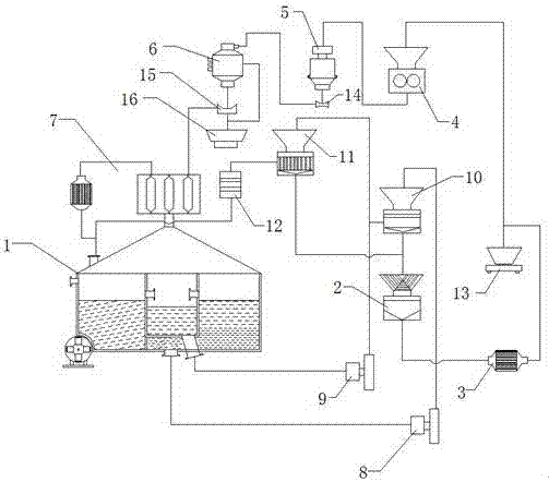
[0040] Such as Figure 1 to Figure 3 As shown, a nano-scale molybdenum disulfide production system includes a reaction sedimentation tank 1, a cleaning device 2, a vacuum dryer 3, a crusher 4, a powder crusher 5 and a gas-solid reactor 6.

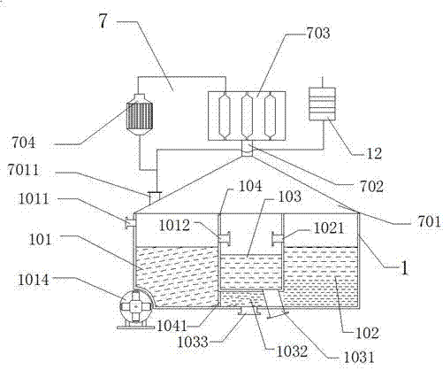
[0041] The reaction sedimentation tank 1 comprises a reaction tank 101, a concentration tank 102, a supernatant liquid pool 103 between the reaction tank 101 and the concentration tank 102, and a waste gas recovery device 7 on the top of the reaction tank 101. The reaction sedimentation tank 1 is used for Reaction and precipitation intermediates such as figure 2 As shown, the reaction pool 101, the supernatant pool 103 and the concentration pool 102 are arranged in sequence, and they are isolated from each other by the isolation plate 104. The upper side of the reaction pool 101 is provided with a raw material inlet 1011, which is used for raw materials to enter the reaction pool. In 101, the other side is provided with a clear liquid out...

Embodiment 2

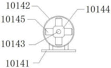
[0068] Embodiment two is the same as embodiment one, and its difference is that the structure of reaction sedimentation tank 1 is different, as Figure 4 As shown, the reaction sedimentation tank 1 includes a reaction tank 101 and a concentration tank 102. At least one bottom of the reaction tank 101 is recessed to form an inner recess 1013, and the inner recess 1013 is equipped with a permanent magnetic induction device 1014 that drives the solution to flow obliquely. The bottom of 102 is provided with slurry outlet 1033, reaction tank 101 and concentration tank 102 are separated by isolation plate 104, and isolation plate 104 bottom is provided with slidable movable plate 1041 or switch valve, and reaction tank 101 is connected with movable plate 1041 or switch valve. The concentration tank 102 is connected, the slurry outlet 1033 is connected to the slurry pump B9, and the output port of the slurry pump B9 is connected to the plate and frame filter 11, that is, the pressure ...


PUM


Abstract

The invention discloses a production system and a production method of nanoscale molybdenum disulfide. The production system comprises a reaction sedimentation tank, wherein the reaction sedimentation tank comprises an exhaust gas recovery device arranged at the upper part of the reaction sedimentation tank and comprises a sealing flange and a three-level alkali liquor absorption tower which is connected with an evaporator, and the evaporator is connected with a reaction material inlet; a feed port of a pressure filter is connected with a slurry pump A, and a filtrate outlet of the pressure filter is connected with a plate and frame filter; a feed port of the plate and frame filter is connected with a slurry pump B, a filtrate outlet of the plate and frame filter is connected with a membrane separation device, and a filtrate outlet of the membrane separation device is connected with the reaction material inlet. The productive rate and the yield of the production system are remarkably higher than those in the prior art, an earnings ratio of the production system is high, the profit space is large, the quality of obtained products is high, and the feasibility is good. Meanwhile, the production system hardly discharges toxic effluent and toxic exhaust gas outwards, realizes green production and is worthy of popularization and application.

Description

technical field [0001] The invention relates to the field of production and preparation of nanometer molybdenum disulfide, in particular to a production system and a production method of nanometer molybdenum disulfide. Background technique [0002] Nano-molybdenum disulfide has unique physical and chemical properties due to its special structure, and is widely used in petroleum hydrodesulfurization, non-aqueous lithium batteries, high-elastic new materials and their coatings, and photoelectrochemical cells. At present, there are many preparation methods for nano-molybdenum disulfide, but most of the preparation methods can only be limited to the laboratory, and there are relatively few methods that can achieve industrial-scale production. Most of them use chemical synthesis, thermal decomposition and oxidation methods. etc., the thermal decomposition method is generally by pyrolysis of MoS 3 To obtain the target product, the preparation process, equipment and operation of t...

Claims


Application Information

Patent Timeline
Patent Type & Authority Patents(China)
IPC IPC(8): C01G39/06B01D53/78B01D53/52
CPCB01D53/52B01D53/78B01D2259/124C01G39/06C01P2004/62C01P2006/80
Inventor 马明哲
Owner 玛雅森林(北京)国际科技有限公司
Why Eureka
Try Eureka