Device and method for removing pollutants in flue gas

A pollutant and flue gas technology, applied in separation methods, chemical instruments and methods, gas treatment, etc., can solve the problems of neglecting the synergistic dust removal function of the desulfurization system, high investment in flue gas treatment, and inability to meet the requirements of ultra-low emissions. Achieve the effect of inhibiting the generation of SO3, reducing investment and operating costs, and improving dust removal efficiency

Inactive Publication Date: 2017-03-08
JIANGSU KEHANG ENVIRONMENT ENG TECH
View PDF0 Cites 6 Cited by
  • Summary
  • Abstract
  • Description
  • Claims
  • Application Information

AI Technical Summary

Problems solved by technology

[0003] The current coal-fired boilers are equipped with dust removal, denitrification, desulfurization and wet electrostatic precipitator systems. Since the dust removal, denitrification and desulfurization systems are provided by different suppliers and are independent of each other, the collaborative dust removal function of the desulfurization system was ignored during the implementation of the project. Leading to high investment in flue gas treatment, and still can not meet the requirements of ultra-low emissions

Method used


Image

  • Device and method for removing pollutants in flue gas
  • Device and method for removing pollutants in flue gas
  • Device and method for removing pollutants in flue gas

Examples


Embodiment 1

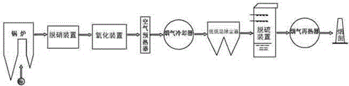
[0052] Such as Figure 1~Figure 3 As shown, this specific embodiment provides a device for removing pollutants in flue gas, including a boiler, and the flue gas of the boiler passes through a denitration device, an oxidation device, an air preheater, a flue gas cooler, and a low-temperature dust collector in sequence. , desulfurization device and flue gas reheater, and then discharged from the chimney.

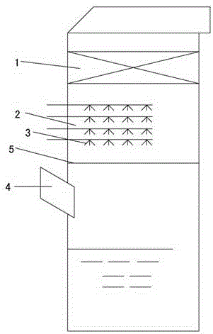
[0053] The desulfurization device includes a desulfurization tower, the top of the desulfurization tower is provided with a high-efficiency demister 1, and a number of spray layers 2 for spraying water are provided under the high-efficiency demister 1, and each of the spray A number of nozzles 3 are arranged on each layer 2, and a flue gas inlet 4 is arranged in the middle of the desulfurization tower; a flue gas uniform distribution device 5 is arranged between the top of the flue gas inlet 4 and the spray layer 2 on the lowermost layer.

[0054] The spray layer is 2 layers....

Embodiment 2

[0070] Embodiment 2: as Figure 1~Figure 3 As shown, this specific embodiment provides a device for removing pollutants in flue gas, including a boiler, and the flue gas of the boiler passes through a denitration device, an oxidation device, an air preheater, a flue gas cooler, and a low-temperature dust collector in sequence. And desulfurization device, and then discharged from the chimney.

[0071] The desulfurization device includes a desulfurization tower, the top of the desulfurization tower is provided with a high-efficiency demister 1, and a number of spray layers 2 for spraying absorption liquid are provided under the high-efficiency demister 1, and each spray A number of nozzles 3 are arranged on the spray layer 2, and a flue gas inlet 4 is arranged in the middle of the desulfurization tower; a flue gas uniform distribution device 5 is arranged between the top of the flue gas inlet 4 and the spray layer 2 on the lowermost layer .

[0072] The spray layer is 4 layers...

Embodiment 3

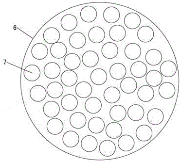
[0087] Embodiment 3: as Figure 1~Figure 3 As shown, the difference between this embodiment and embodiment 1 is that the spray layer is 3 layers; the area of ​​all the small holes 7 accounts for 40% of the area of ​​the flat plate 6; the cooling temperature of the flue gas cooler is 85 ℃; the strong oxidant is sodium hypochlorite solution; the auxiliary agent is calcium chloride solution.


PUM


Abstract

The invention provides a device and a method for removing pollutants in flue gas. The device comprises a boiler, wherein the flue gas from the boiler sequentially passes by a denitration device, an oxidation device, an air preheater, a flue gas cooler, a low-low temperature dust remover, a desulfurizer and a flue gas reheater and is discharged from a chimney. Nitrogen oxide and mercury in the flue gas can be removed simultaneously in the desulfurization process; free mercury in the flue gas is oxidized with a strong oxidizer before the flue gas enters an ammonia desulfurization system, ionic Hg<2+> is fixed by an properly supplemented aid, and Hg<2+> is removed together with the flue gas in a dust removal system; the environment-friendly requirements can be met with an SNCR process instead of a high-investment SCR process after NOX is oxidized, and investment is reduced; a low-low temperature dust removal technology is adopted, the concentration of flue gas dust at an inlet of a desulfurization system is reduced, and the desulfurization system can meet the requirement for ultralow emission without adopting wet-type electric precipitation.

Description

technical field [0001] The invention relates to a device and method for removing pollutants in flue gas, in particular to a device and method for simultaneously removing nitrogen oxides and mercury in flue gas during ammonia desulfurization. Background technique [0002] According to the requirements of the State Council's "Coal Power Energy Conservation and Emission Reduction Upgrade and Action Transformation Plan (2014-2020)" and the Ministry of Environmental Protection's "Comprehensive Implementation of Coal-fired Power Plant Ultra-low Emissions and Energy Conservation Transformation Work Plan", the emission concentration limit of air pollutants is within the benchmark Under the condition of 6% oxygen content, the emission concentrations of soot, sulfur dioxide, and nitrogen oxides are not higher than 10, 35, and 50 mg / m3 respectively. [0003] The current coal-fired boilers are equipped with dust removal, denitrification, desulfurization and wet electrostatic precipitato...

Claims


Application Information

Patent Timeline
Patent Type & Authority Applications(China)
IPC IPC(8): B01D53/75B01D53/60B01D53/78B01D53/50B01D53/00B01D53/06
CPCB01D53/002B01D53/06B01D53/50B01D53/60B01D53/75B01D53/78B01D2251/104B01D2251/106B01D2251/108B01D2257/30B01D2257/302B01D2257/40B01D2257/602B01D2258/0283Y02A50/20
Inventor 刘怀平李承泉刘季平耿桂淦朱冲李海翠
Owner JIANGSU KEHANG ENVIRONMENT ENG TECH
Why Eureka
Try Eureka