Composite automobile exhaust particle filtering device

A technology for automobile exhaust and particle filtration, which is applied to exhaust devices, electronic control of exhaust treatment devices, diagnostic devices of exhaust treatment devices, etc., can solve the problems of large filtering resistance, insufficient filtering capacity, and fast exhaust gas flow rate, Achieve the effect of improving filtration efficiency, facilitating filtration and collection, and reducing energy consumption

Inactive Publication Date: 2017-04-19
HUAZHONG UNIV OF SCI & TECH
View PDF8 Cites 3 Cited by
  • Summary
  • Abstract
  • Description
  • Claims
  • Application Information

AI Technical Summary

Problems solved by technology

However, most of the existing DPF filter element materials are mainly cordierite and silicon carbide. This kind of filter body has the following disadvantages: (1) long-term use of filter resistance, high price, difficult to recycle after discarding, (2) The requirements for oil quality are high, and low-sulfur and low-ash diesel oil is required. (3) Frequent short-distance operation will affect regeneration and easy thermal cracking and other issues
However, this type of product also has the problem of insufficient filtration efficiency. In addition, due to the limitation of the structure itself, under the high-load operation of the engine, due to the fast exhaust flow rate and high concentration of exhaust particles, the problem of insufficient filtration capacity will also occur.
[0005] To sum up, the current existing various filter elements or simply adding electrostatic filtration cannot fully meet the needs of exhaust emissions

Method used


Image

  • Composite automobile exhaust particle filtering device
  • Composite automobile exhaust particle filtering device
  • Composite automobile exhaust particle filtering device

Examples


Embodiment 1

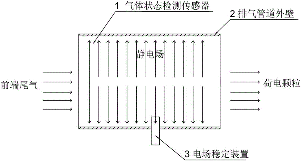
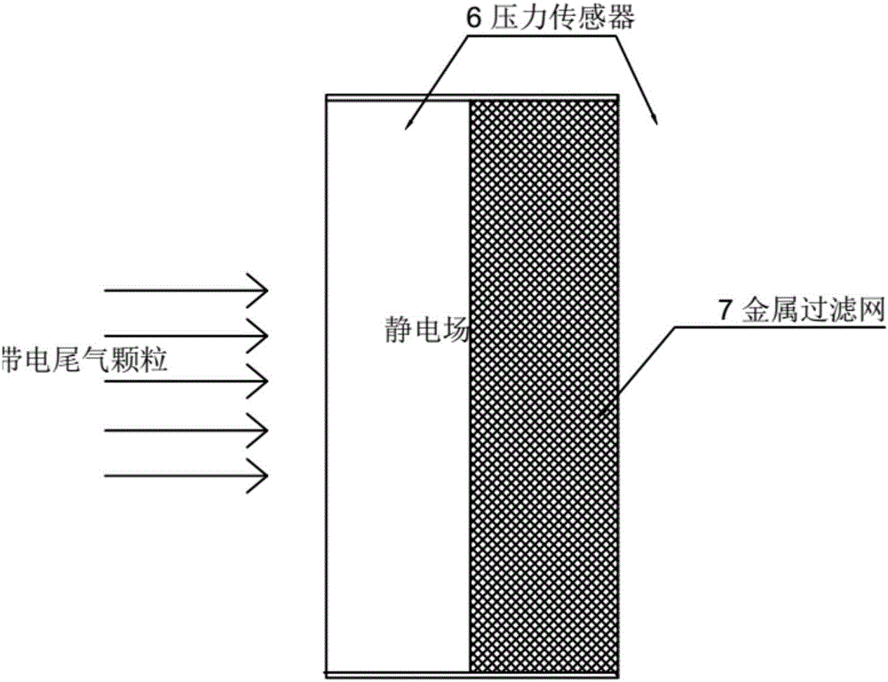
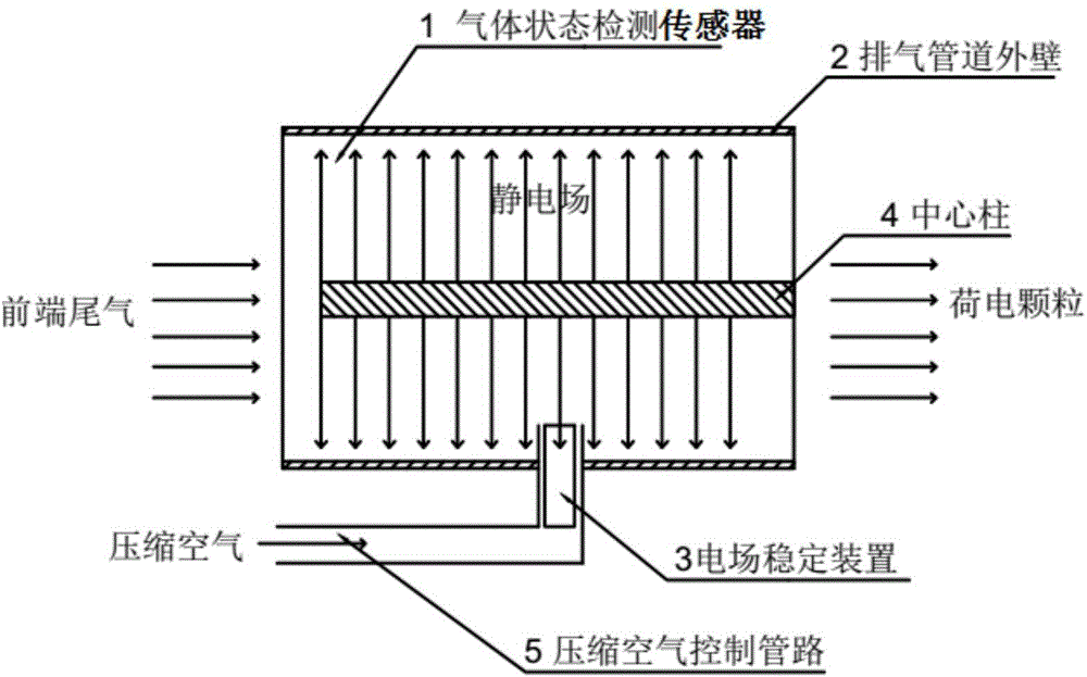
[0040] Such as image 3 As shown, a composite vehicle exhaust particle filter device, the device includes a gas state detection sensor 1 arranged at the intake end of the exhaust pipe, an outer wall of the exhaust pipe 2 and an electric field stabilization device 3, along the exhaust pipe in the exhaust pipe There is a central column 4 in the direction of the pipeline axis, the central column 4 is connected to the high-voltage positive electrode, and the outer wall of the exhaust pipe 2 is grounded, so that an electrostatic field is formed in the exhaust pipe to pre-charge the exhaust particles. There is a metal filter screen 7 to collect exhaust gas particles, and the exhaust gas enters the metal filter screen after being pre-charged;

[0041] The electric field stabilizing device 3 made of ceramic body is arranged at the bottom of the exhaust pipe, and the electric field stabilizing device 3 is in the compressed air control pipeline 5, and compressed air is passed into the c...

Embodiment 2

[0043] Such as Figure 4 As shown, a composite vehicle exhaust particle filter device, the device includes a gas state detection sensor 1 arranged at the intake end of the exhaust pipe, an outer wall of the exhaust pipe 2 and an electric field stabilization device 3, and is parallel to the exhaust pipe in the exhaust pipe. There are multiple poles 8 arranged on the axis of the gas pipeline, and one end of the poles 8 passes through the metal filter 7. The poles 8 are connected to the high-voltage positive pole, and the outer wall 2 of the exhaust pipe is grounded, thereby forming static electricity in the exhaust pipe. Pre-charge the exhaust particles in the field, and a metal filter 7 is installed at the outlet of the exhaust pipe to collect the exhaust particles. After the exhaust gas is pre-charged, it enters the metal filter;

[0044] The electric field stabilizing device 3 made of ceramic body is arranged at the bottom of the exhaust pipe, and the electric field stabilizi...

Embodiment 3

[0046] Such as Figure 5 As shown, a composite vehicle exhaust particle filtering device, the device includes a gas state detection sensor 1 arranged at the intake end of the exhaust pipe, an outer wall of the exhaust pipe 2 and an electric field stabilization device 3, parallel to the metal in the exhaust pipe The polar plate 9 provided by the filter screen 7 is connected to the high-voltage positive electrode, and the outer wall 2 of the exhaust pipe is grounded, so that an electrostatic field is formed in the exhaust pipe to pre-charge the exhaust particles. A metal filter screen 7 is provided to form an electrostatic field in the metal filter screen 7, and then the particles are collected under the joint action of the metal filter screen and the static electricity;

[0047] The electric field stabilizing device 3 made of ceramic body is arranged at the bottom of the exhaust pipe, and the electric field stabilizing device 3 is in the compressed air control pipeline 5, and c...


PUM


Abstract

The invention belongs to the field of electrostatic-type exhaust treatment systems and discloses a composite automobile exhaust particle filtering device. The device is characterized in that an electric charging device is disposed in an exhaust pipeline; the electric charging device is connected to a high-voltage positive electrode; the outer wall of the exhaust pipeline is connected to a grounding electrode; an electrostatic field is formed in the exhaust pipeline to conduct pre-charging of exhaust particles; a metal filtering screen is disposed at a discharge hole of the exhaust pipeline to collect the exhaust particles; the electric charging device is a center pillar, multiple parallel electrode pillars or an electrode board; and devices such as an electric field stabilization device, a compressed air control pipeline, a gas state detection sensor and a pressure sensor are also disposed on the exhaust pipeline to promote electric field stabilization and collect the exhaust particles. The filtering device disclosed by the invention has the advantages that a demand for exhaust filtering under different loads, especially heavy loads, can be satisfied; the electric charging capability of a filtering system can be enhanced effectively, and particle collection can be perfected; filtering performance can be improved; the efficiency is high; and the filtering performance is stable.

Description

technical field [0001] The invention belongs to the field of electrostatic tail gas treatment systems, and more specifically relates to a compound automobile exhaust particle filter device, which can improve the filter performance of the filter and has the advantages of high filter efficiency and stable filter performance. Background technique [0002] The concentration and exposure time of particulate matter in the atmosphere are the key factors that determine the inhalation amount and the degree of harm of particulate matter. Fine particulate matter is rich in toxic and harmful substances, and has a long residence time in the atmosphere, a long transportation distance, and a long exposure time. Therefore, it is harmful to the human body. Health and atmospheric environmental quality have even greater impacts. According to the "2013 Motor Vehicle Pollution Prevention and Control Annual Report" released by the Ministry of Environmental Protection in early 2014, diesel vehicle...

Claims


Application Information

Patent Timeline
Patent Type & Authority Applications(China)
IPC IPC(8): F01N3/01F01N3/035F01N11/00
CPCF01N3/01F01N3/035F01N11/00F01N2250/02Y02T10/40
Inventor 夏卫生孟学伟田文扬夏盼盼
Owner HUAZHONG UNIV OF SCI & TECH
Why Eureka
Try Eureka