Catalytic reduction combined denitrification system

A reduction method and denitration technology, applied in the field of catalytic reduction method compound denitration system, can solve the problems of secondary pollution and increase production cost, and achieve the effects of reducing NOx production, reducing consumption and optimizing operating parameters.

Active Publication Date: 2020-05-22
北京绿岩环保科技有限责任公司 +1
View PDF6 Cites 0 Cited by
  • Summary
  • Abstract
  • Description
  • Claims
  • Application Information

AI Technical Summary

Problems solved by technology

[0002] According to the data released by China Cement Network and China Cement Association: In 2012, my country's annual cement production capacity has reached 2.5 billion tons, and there are more than 2,000 new dry-process cement clinker production lines. Nitrogen oxides account for 15% to 20% of the total emissions of nitrogen oxides, and the control of nitrogen oxides and sulfide emissions in cement manufacturing enterprises is imminent. Currently, cement manufacturing enterprises mostly use staged combustion, SNCR denitrification, ammonia desulfurization and calcium desulfurization modes to reduce pollution However, the ammonia escape caused by the above-mentioned process will cause secondary pollution to the atmosphere. Therefore, it is an inevitable trend to improve and improve the above-mentioned process to effectively reduce the emission of nitrogen oxides and reduce the ammonia escape generated in the process of nitrogen oxide treatment.
Moreover, in the current SNCR denitrification process, the consumption of reducing agent ammonia water (20% content) is roughly 3-5 kg / t clinker, the ammonia escape is about 5-12PPm, and the denitrification cost per ton of clinker is 2-5 yuan / t, resulting in cement Enterprises increase production costs by 3-8 million yuan per year

Method used


Image

  • Catalytic reduction combined denitrification system
  • Catalytic reduction combined denitrification system
  • Catalytic reduction combined denitrification system

Examples


Embodiment Construction

[0027] The technical solutions of the present invention will be further described below in conjunction with the accompanying drawings and specific embodiments.

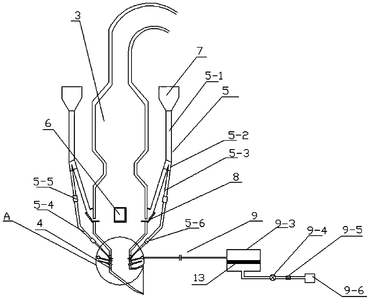
[0028] Such as Figure 1-Figure 6 As shown, the catalytic reduction composite denitrification system of the present invention includes a rotary kiln, a kiln tail smoke chamber, a smoke chamber flue and a decomposition furnace, and the system also includes a smoke chamber flue extension pipe, a low-nitrogen burner, and a kiln tail steam Catalytic device, tertiary air inlet and C4 feeding pipe;

[0029] The C4 feeding pipe includes 2 symmetrically arranged feeding pipes, 2 distribution valves and 2 feeding branch pipes, and the 2 feeding branch pipes are composed of 2 upper branch pipes and 2 lower branch pipes,

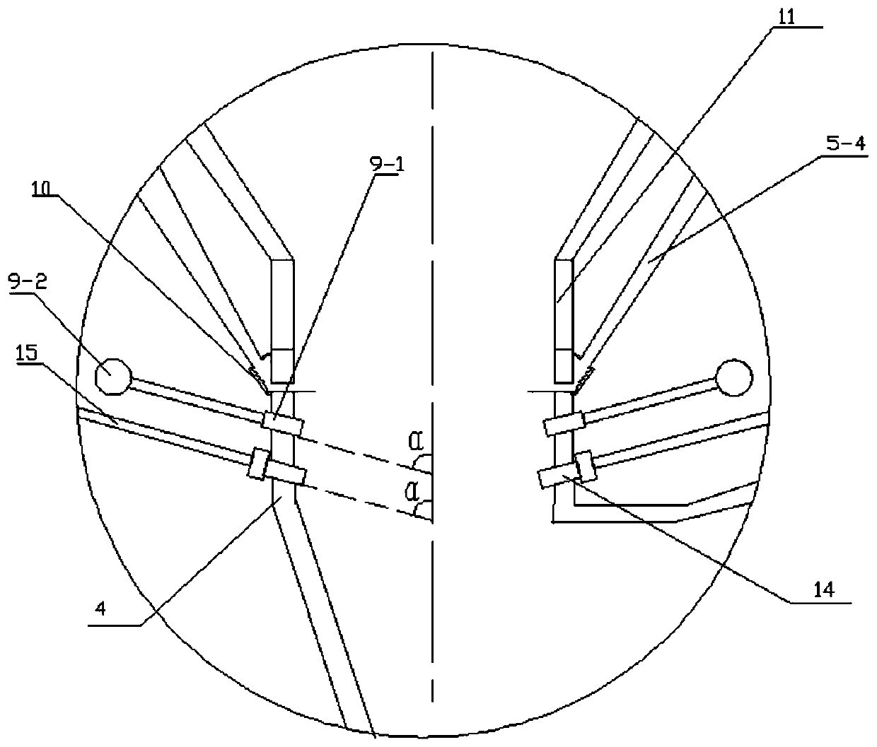
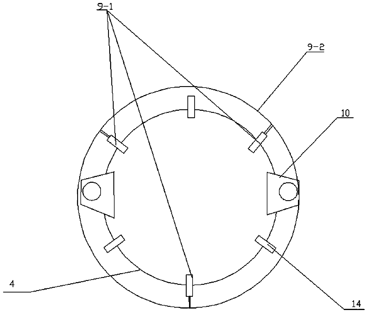
[0030] The steam catalytic device at the kiln tail includes 3 steam nozzles, an annular pipe, an air inlet pipe, a steam catalyst tank, a flow meter, a control valve, a steam source and a catalyst;

[0031]T...


PUM

PropertyMeasurementUnit
lengthaaaaaaaaaa
diameteraaaaaaaaaa
lengthaaaaaaaaaa

Abstract

The invention relates to a special type catalytic reduction method composite denitration system. The system comprises a rotary kiln, a kiln tail smoke chamber arranged at the tail of the rotary kiln and a decomposing furnace, and further comprises a smoke chamber flue extending pipe, a low-nitrogen burner, a kiln tail steam catalytic unit, a tertiary air inlet and a C4 discharging pipe; the C4 discharging pipe comprises two symmetrically-arranged discharging pipe bodies, two dividing valves and two discharging branch pipes, and the two discharging branch pipes are composed of two upper branch pipe bodies and two lower branch pipe bodies; and the kiln tail steam catalytic unit comprises three steam spraying nozzles, an annular pipe, a steam catalyst tank, a flowmeter, a control valve, a steam source and a catalyst. On the premise that nitrogen oxide emission is unchanged, the using amount of a reducing agent, namely ammonium hydroxide of the SNCR denitration system can be saved by 50% to 100%, and ammonia escape is reduced by 5 milligrams per cubic meter to 10 milligrams per cubic meter. Pollution of nitrogen oxide emission to the atmosphere is effectively avoided, no new pollution source is generated, and the very good application and popularization value can be achieved.

Description

technical field [0001] The invention belongs to the technical field of environmental protection, and in particular relates to a catalytic reduction composite denitrification system suitable for a dry cement clinker production line. Background technique [0002] According to the data released by China Cement Network and China Cement Association: In 2012, my country's annual cement production capacity has reached 2.5 billion tons, and there are more than 2,000 new dry-process cement clinker production lines. Nitrogen oxides account for 15% to 20% of the total emissions of nitrogen oxides, and the control of nitrogen oxides and sulfide emissions in cement manufacturing enterprises is imminent. Currently, cement manufacturing enterprises mostly use staged combustion, SNCR denitrification, ammonia desulfurization and calcium desulfurization modes to reduce pollution However, the ammonia escape caused by the above-mentioned process will cause secondary pollution to the atmosphere. T...

Claims


Application Information

Patent Timeline
Patent Type & Authority Patents(China)
IPC IPC(8): F27B7/34F27D17/00F23D1/02B01D53/90B01D53/56
CPCB01D53/8625B01D53/90B01D2251/20B01D2258/0283F23D1/02F27B7/34F27D17/008Y02A50/20Y02P10/25
Inventor 孙晋国刘春乐吴俊亮马超王朋
Owner 北京绿岩环保科技有限责任公司
Why Eureka
Try Eureka