

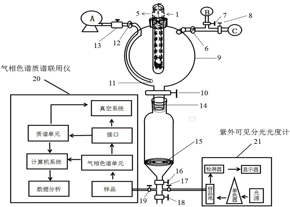
Device capable of carrying out real-time separation and detection on photocatalytically degraded product of pollutant
A technology for real-time separation and degradation products, applied in measuring devices, material separation, color/spectral characteristic measurement, etc., can solve the problems of complex separation system, difficult operation, and imperfect detection, etc., achieve convenient reaction conditions and realize real-time separation Effect
- Summary
- Abstract
- Description
- Claims
- Application Information
AI Technical Summary
Problems solved by technology
Method used
Image

Examples
Embodiment 1
[0050] Example 1 Real-time separation of liquid phase fragments of degradation products and detection by UV-Vis photometer
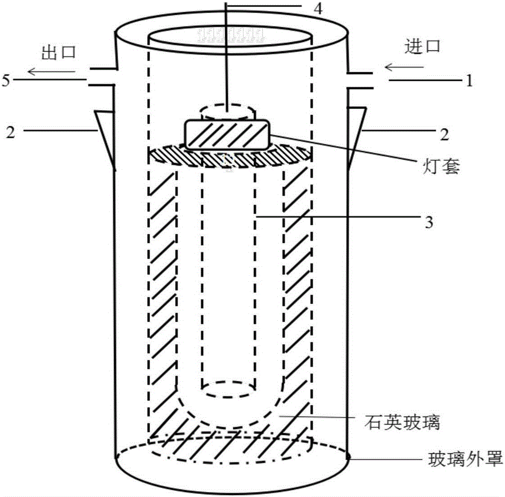
[0051] 1) Choose an ordinary glass chromatography column with a diameter of 40mm and an effective length of 203mm, and install it in advance. Make sure that the light source is a xenon lamp, replace it with a xenon lamp tube, and inject condensed water;
[0052] 2) Close the drain valve 10, and make p25 (100mg) and 100mL concentration 1×10 -5 mol / L Rhodamine B is mixed and added to the photocatalytic reaction device;
[0053] 3) Turn on the pump A, and let in the air, and do a corresponding test at the air outlet;
[0054] 4) Turn on the lamp source current knob, adjust the current, and make the current stable at 9A;
[0055] 5) After photoreaction for a period of time, close the bottom valve 16, open the discharge valve 10, take a sample, find the corresponding developing agent by thin layer chromatography (TLC), the stationary phase is 200-300 mesh s...
Embodiment 2
[0058] Example 2 Real-time separation of liquid phase fragments of degradation products and detection by gas chromatography-mass spectrometry
[0059] 1) Choose a plexiglass chromatography column with a diameter of 46mm and an effective length of 203mm, and install it in advance. Make sure that the light source is a xenon lamp, replace it with a xenon lamp tube, and inject condensed water;
[0060] 2) Close the drain valve 10, and the concentration of cobalt porphyrin catalyst (100mg) and 100mL is 1×10 -4 After mixing mol / L p-nitroaniline, add it into the photocatalytic reaction device;
[0061] 3) Turn on the pump A, and let in the air, and do a corresponding test at the air outlet;
[0062] 4) Turn on the lamp source current knob, adjust the current, and make the current stable at 8A;
[0063] 5) After photoreaction for a period of time, close the bottom valve 16, open the discharge valve 10, take a sample, find the corresponding developing agent with thin layer chromatogr...
Embodiment 3
[0066] Example 3 Degradation product gas phase fragment detection
[0067] 1) Choose an ordinary glass chromatography column with a diameter of 40mm and an effective length of 254mm, and install it in advance, determine the light source as an ultraviolet lamp, replace it with an ultraviolet lamp, adjust a certain intensity, and feed condensed water;
[0068] 2) Close the drain valve 10, and make p25 (100mg) and 100mL concentration 1×10 -5 mol / L formaldehyde is mixed and added to the photocatalytic reaction device;
[0069] 3) Close the intake valve 13, the ultraviolet detection valve 7, observe the air outlet flowmeter 6, open the carbon dioxide measuring instrument valve 8, and can monitor in real time by the carbon dioxide measuring instrument C (its sensitivity is 0.1ppm, and the detection range is 0 to 10000ppm), so it can Calculate the mineralization rate;
[0070] 4) After the reaction, purify and disinfect the reaction device (determine the light source as an ultravio...
PUM
| Property | Measurement | Unit |
|---|---|---|
| Sensitivity | aaaaa | aaaaa |
Abstract
Description
Claims
Application Information