
Electrolysis electrosparking method using planar thin metal sheet electrode

A technology of planar electrodes and processing methods, which is applied in the field of micromachining and can solve problems such as the inability to fully meet the needs of electrolytic sparks.

Inactive Publication Date: 2017-06-20
HARBIN INST OF TECH SHENZHEN GRADUATE SCHOOL
View PDF8 Cites 26 Cited by
  • Summary
  • Abstract
  • Description
  • Claims
  • Application Information

AI Technical Summary

Problems solved by technology

[0004] Gap control has always been a difficult problem in electrolytic EDM. At present, ball screw plus AC servo motor or linear motor is the mainstream servo drive device. With the advancement of technology, the precision of these two drive mechanisms is also continuously improving. Linear motors with precision grating scales can achieve high feed accuracy, but independent use still cannot fully meet the requirements of electrolytic EDM precision servo feed and stable processing

Method used


Image

  • Electrolysis electrosparking method using planar thin metal sheet electrode
  • Electrolysis electrosparking method using planar thin metal sheet electrode
  • Electrolysis electrosparking method using planar thin metal sheet electrode

Examples


Embodiment 1

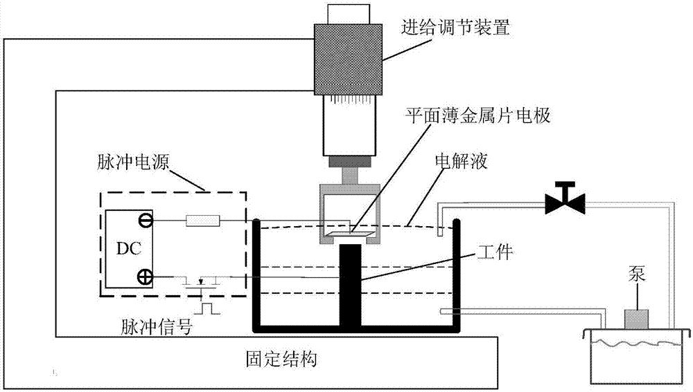
[0029] An electrolytic spark discharge machining device using a flat thin metal sheet electrode, comprising: a fixed structure, a feed adjustment device, a pulse power supply, a flat thin metal sheet electrode, a workpiece, and a solution tank, the feed adjustment device is fixed on the fixed structure, The flat thin metal sheet electrode is installed under the feed adjustment device, and the workpiece is installed in the solution tank under the flat thin metal sheet electrode. The feed adjustment device is driven by a servo motor, and the macro feed of the vertical position of the electrode can be realized through program control. The distance between the thin metal sheet and the workpiece is 5μm-50μm; the thin metal sheet and the workpiece form a capacitor C, and the thin metal sheet and the workpiece are the two poles of the capacitor C, and the two poles are respectively connected to the pulse power supply to form an electrolytic cell. The pulse power supply voltage is about...

Embodiment 2

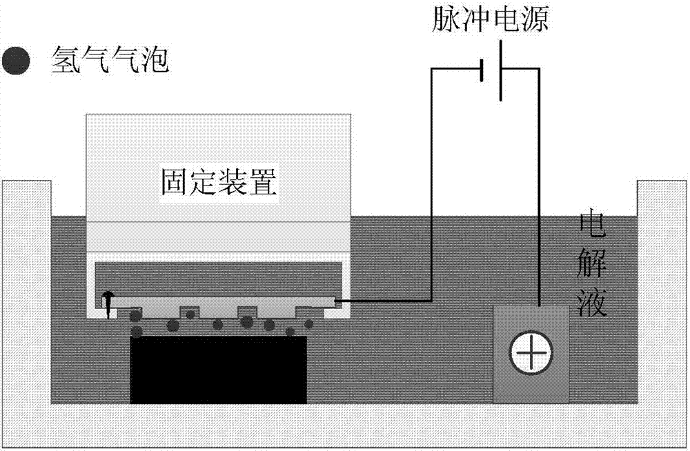
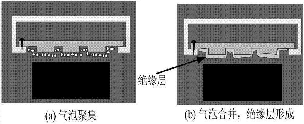
[0033] Adopt the processing method of embodiment 1 processing device, preferred step (1) electrolytic reaction stage, as figure 2 As shown, it includes, feeding close to the workpiece through the adjusting device, immersing the plane thin metal sheet electrode (tool) electrode in the electrolyte, and the tool electrode is connected to the negative pole of the pulse power supply as the cathode of the electrolytic reaction. The positive electrode of the pulse power supply is connected to the workpiece as the anode of the electrolytic reaction. After the pulse power supply is energized, a potential difference is generated between the tool electrode and the auxiliary electrode, and the positive ions in the electrolyte move to the tool electrode (cathode), and the negative ions move to the workpiece (anode). , so that a chemical reaction occurs in the electrolyte. Hydrogen gas bubbles begin to be generated around the flat thin metal sheet (cathode) as the tool electrode, and the g...

Embodiment 3

[0039] As a preferred solution of the processing method in Example 2, the present invention first processes a micro electrode on a flat thin metal sheet by micro electric discharge machining or fused deposition molding method, and adopts a metal bridge structure of a curved cantilever to be installed under the feeding device , the designed feeding device realizes the macro-feeding movement of the electrode position through motor adjustment. The pulse signal is used to control the MOSFET switch to control the charge between the flat thin metal sheet electrode and the workpiece, and the electrostatic force is used to make the metal bridge structure with curved cantilever connected to the metal sheet deform and displace, so as to realize the micro-feed of the vertical position of the electrode.


PUM

PropertyMeasurementUnit
thicknessaaaaaaaaaa
widthaaaaaaaaaa
lengthaaaaaaaaaa

Abstract

The invention belongs to the field of micro machining, and particularly relates to an electrolysis electrosparking method and device using a planar thin metal sheet electrode. The machining process of the designed device comprises five stages of electrolysis reaction for bubble production, bubble gathering and insulation layer forming, planar electrode bending deformation and discharge channel forming, material corrosion removal and ejection, and deionization and electrode deformation recovery. Micro feeding of the electrode position in machining is achieved, and the gap control problem in electrolysis electrosparking is solved. Compared with a traditional single-point discharge machining method, the planar thin metal sheet electrode can achieve discharge machining of the whole plane, the machining efficiency is greatly improved, the device is simple in structure and low in cost, and the high-precision low-cost high-efficiency micro machining method can be achieved and has the important theoretical significance and engineering application value.

Description

technical field [0001] The invention belongs to the field of micromachining, and in particular relates to an electrolysis electric spark machining method and a device thereof using planar thin metal sheet electrodes. Background technique [0002] With the wide application of micro-sized products in the fields of micro-electromechanical systems, microfluidics, and biomedical testing systems, the processing of micro-components has received great attention. In order to find high-efficiency, high-precision, and low-cost micro-parts processing solutions in modern industry, researchers use special processing technologies such as EDM and electrolytic processing, as well as micro-processing technologies based on photolithography. In low-volume processing, specialty processing techniques are more economical than photolithography. Special processing technology uses energy such as electric energy, heat energy, light energy, electrochemical energy, chemical energy, sound energy and spe...

Claims


Application Information

Patent Timeline
Patent Type & Authority Applications(China)
IPC IPC(8): B23H5/02B23H9/00
CPCB23H5/02B23H9/00
Inventor 黄瑞宁王琨宁李兴赵呈路楼云江
Owner HARBIN INST OF TECH SHENZHEN GRADUATE SCHOOL
Learn More