
Continuous conducive in-situ C/metal solid solution/Ce<4+>-doped CuF<2> positive electrode and preparation method

A solid solution, metal technology, applied in battery electrodes, circuits, electrical components, etc., can solve the problems of complex mechanism, unpredictable effects, high polarization voltage, etc., to reduce kinetic obstacles, avoid side reaction products, and improve electrons. The effect of conductivity

Inactive Publication Date: 2017-07-14
宁波吉电鑫新材料科技有限公司
View PDF1 Cites 0 Cited by
  • Summary
  • Abstract
  • Description
  • Claims
  • Application Information

AI Technical Summary

Problems solved by technology

However, there are still very few reports on copper fluoride materials as cathode materials for lithium-ion batteries. The main difficulty is that the electrochemical properties of copper fluoride are closely related to the preparation process and have poor repeatability; at the same time, copper fluoride materials in organic electrolytes The medium stability is not enough; it also has a negative characteristic that the electronic conductivity is extremely low, so it will lead to a high polarization voltage during the charge and discharge process, although some researchers use carbon black mixed ball milling to improve the conductivity of the material However, it is still difficult for granular carbon black to form a complete conductive link, which greatly improves its electronic conductivity.
Finally, the material produces a new phase of metallic copper and lithium fluoride during discharge, and the small particles of the new phase are kinetically disadvantaged in the initial formation stage, so the maintenance of the subsequent charge-discharge capacity, discharge potential, and charge-discharge capacity ability to adversely affect
Ion doping is also an effective way to adjust the microstructure of the lattice and change the electron and ion transport characteristics of the lattice. However, the mechanism of ion doping or even multi-ion synergistic doping on the matrix is ​​very complicated, and the effect is often difficult. expected

Method used


Image

  • Continuous conducive in-situ C/metal solid solution/Ce&lt;4+&gt;-doped CuF&lt;2&gt; positive electrode and preparation method

Examples


Embodiment 1

[0013]Example 1: The preparation composition is 5wt% copper nitrate, 0.1wt% cerium ammonium nitrate, 6wt% acrylamide, 1wt% N, N'-methylenebisacrylamide starting aqueous solution, using polytetrafluoroethylene stirring paddle to Stir at 900 rpm for 5 minutes. The initial aqueous solution was raised to 75°C at a rate of 5°C / min and maintained at this temperature until the initial aqueous solution became a jelly-like gel. Dry the formed gel in a low-temperature and high-vacuum environment. The drying process adopts the finished freeze dryer on the market. Put the gel into the sample tray of the freeze dryer and start the refrigerator. Reduce to minus 45°C, turn on the vacuum pump to increase the vacuum degree, wait until the gas pressure in the system drops below 25Pa, turn on the partition temperature control to start dehydration and drying, other operating parameters adopt the machine preset value, after the air pressure in the system is stabilized and the drying is completed, ...

Embodiment 2

[0014] Embodiment 2: The preparation composition is the initial aqueous solution of 15wt% copper nitrate, 0.5wt% cerium ammonium nitrate, 12wt% acrylamide, 2wt% N, N'-methylenebisacrylamide, using polytetrafluoroethylene stirring paddle to Stir at 1200 rpm for 15 minutes. The initial aqueous solution was raised to 85°C at a rate of 10°C / min and maintained at this temperature until the initial aqueous solution became a jelly-like gel. Dry the formed gel in a low-temperature and high-vacuum environment. The drying process adopts the finished freeze dryer on the market. Put the gel into the sample tray of the freeze dryer and start the refrigerator. Reduce to minus 50°C, turn on the vacuum pump to increase the vacuum degree, wait for the gas pressure in the system to drop below 32Pa, turn on the temperature control of the clapboard to start dehydration and drying, other operating parameters adopt the machine preset value, after the air pressure in the system is stabilized and the...

Embodiment 3

[0015] Example 3: Preparation of an initial aqueous solution consisting of 7wt% copper nitrate, 0.3wt% cerium ammonium nitrate, 9wt% acrylamide, and 1.5wt% N, N'-methylenebisacrylamide, using a polytetrafluoroethylene stirring paddle Stir at 1150 rpm for 10 minutes. The initial aqueous solution was raised to 80°C at a rate of 7°C / min and maintained at this temperature until the initial aqueous solution became a jelly-like gel. Dry the formed gel in a low-temperature and high-vacuum environment. The drying process adopts the finished freeze dryer on the market. Put the gel into the sample tray of the freeze dryer and start the refrigerator. Reduce to minus 48°C, turn on the vacuum pump to increase the vacuum degree, wait for the gas pressure in the system to drop below 30Pa, turn on the temperature control of the clapboard to start dehydration and drying, other operating parameters adopt the machine preset value, and after the air pressure in the system is stabilized and the dr...


PUM


Abstract

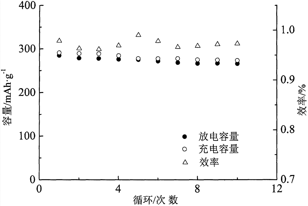
The invention discloses a continuous conducive in-situ C / metal solid solution / Ce<4+>-doped CuF<2> composite copper fluoride lithium ion battery positive electrode material and a preparation method therefor. According to the preparation method, by means of a drying process in a low-temperature and high-vacuum condition and a carbonization and in-situ reduction process under gas protection, a continuous carbon film with holes and a gap structure can be formed; copper fluoride is fixedly formed on the carbon film, and the metal solid solution is subjected to in-situ reduction on the surface of copper fluoride granules in an in-situ manner, so that electronic conductivity of the composite material is greatly improved; a homogeneous crystallization core can be provided for discharging of the electrode material and dynamic obstruction in new phase formation can be lowered; by virtue of Ce<4+> doping, the rate of a discharging reaction can be improved; and meanwhile, generation of multiple kinds of compound salt of copper fluoride and other secondary reaction products in a liquid phase reaction can be avoided, and excellent electrochemical performance is achieved.

Description

technical field [0001] The invention relates to the technical field of a method for manufacturing a high-performance copper fluoride lithium battery cathode material. Background technique [0002] Lithium-ion secondary batteries have the absolute advantages of high volume, weight-to-energy ratio, high voltage, low self-discharge rate, no memory effect, long cycle life, and high power density. Currently, the global mobile power market has an annual share of more than 30 billion US dollars and Gradually grow at a rate of more than 10%. Especially in recent years, with the gradual depletion of fossil energy, new energy sources such as solar energy, wind energy, and biomass energy have gradually become alternatives to traditional energy sources. Among them, wind energy and solar energy are intermittent, and a large amount of energy is used simultaneously to meet the needs of continuous power supply. Energy storage batteries; urban air quality problems caused by automobile exhau...

Claims


Application Information

Patent Timeline
Patent Type & Authority Applications(China)
IPC IPC(8): H01M4/36H01M4/583H01M4/62H01M4/58H01M4/38H01M10/0525
CPCH01M4/362H01M4/38H01M4/58H01M4/583H01M4/625H01M10/0525Y02E60/10
Inventor 水淼
Owner 宁波吉电鑫新材料科技有限公司
Learn More