
High-performance straight-waveguide-type electro-optic phase modulator and preparation method thereof

An electro-optic phase modulation, straight waveguide technology, applied in nonlinear optics, instruments, optics, etc., can solve the problems of inability to meet the high requirements of electro-optic modulation speed and capacity, low electro-optic coefficient, and high half-wave voltage, and achieve excellent phase modulation capability. , Improve device performance, the effect of low half-wave voltage

Active Publication Date: 2017-09-29
XI AN JIAOTONG UNIV
View PDF5 Cites 2 Cited by
  • Summary
  • Abstract
  • Description
  • Claims
  • Application Information

AI Technical Summary

Problems solved by technology

However, the half-wave voltage of these two materials is high, the electro-optic coefficient is low, and the above-mentioned preparation methods require complex processes and large-scale equipment, and the change amount Δn of the optical waveguide refractive index in the preparation method is usually small, so Electro-optic modulation devices developed based on such materials require higher power drivers, which cannot meet the high requirements of electro-optic modulation in terms of speed and capacity.

Method used


Image

  • High-performance straight-waveguide-type electro-optic phase modulator and preparation method thereof
  • High-performance straight-waveguide-type electro-optic phase modulator and preparation method thereof
  • High-performance straight-waveguide-type electro-optic phase modulator and preparation method thereof

Examples


preparation example Construction

[0042] A method for preparing a high-performance direct waveguide type electro-optic phase modulator, comprising the following steps:

[0043] 1. Crystal processing

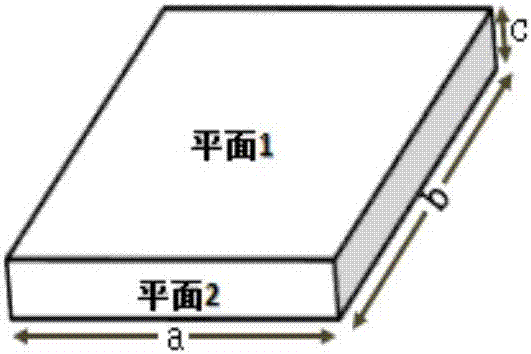
[0044] 1.1. Select a crack-free and well-crystallized area for the tetragonal phase of the [001] crystal orientation, the orthorhombic phase of the [110] crystal orientation, or the trigonal phase PMNT system or PIMNT system of the [111] crystal orientation. Three-dimensional orientation, and cut into the shape required for the experiment (4~10)*(4~10)*(2~4) mm (a*b*c), grind plane 1, plane 2 and their parallel planes and polishing, such as figure 1 shown. Grind lightly with sandpaper until there is no obvious scratch, and then polish it on a polishing machine until it is close to an optical plane (flatness is less than 1 micron) to obtain the sample required for the experiment.

[0045] 2. Annealing

[0046] 2.1. Annealing the tetragonal phase of the [001] crystal orientation, the orthorhombic phase of the [...

Embodiment 1

[0065] 1. Crystal processing

[0066] 1.1. Select a crack-free and well-crystallized region of the relaxor ferroelectric single crystal of the tetragonal phase PMNT system with [001] crystal orientation, and three-dimensionally orientate it, and cut it into the shape required for the experiment 4*10*2 mm (a*b* c), grinding and polishing plane 1, plane 2 and their parallel planes, such as figure 1 shown. Grind lightly with sandpaper until there are no obvious scratches, and then polish it on a polishing machine until it is close to an optical plane (flatness is less than 1 micron) to obtain the sample required for the experiment.

[0067] 2. Annealing

[0068] 2.1. Annealing the relaxation ferroelectric single crystal sample of tetragonal phase PMNT system with the [001] crystal orientation described in step 1 to eliminate the stress generated during growth, cutting, polishing and ferroelectric phase formation. The crystal was placed in an atmosphere furnace, and the tempera...

Embodiment 2

[0085] 1. Crystal processing

[0086] 1.1. Select a crack-free and well-crystallized region of the [110] orthorhombic PIMNT system relaxor ferroelectric single crystal, and cut it into the shape required for the experiment 10*4*3 mm (a*b *c), grind and polish plane 1, plane 2 and their parallel planes, such as figure 1 shown. Grind lightly with sandpaper until there are no obvious scratches, and then polish it on a polishing machine until it is close to an optical plane (flatness is less than 1 micron) to obtain the sample required for the experiment.

[0087] 2. Annealing

[0088] 2.1. Perform annealing treatment on the [110] oriented orthorhombic PIMNT system relaxation ferroelectric single crystal sample described in step 1 to eliminate the stress generated during growth, cutting, polishing and ferroelectric phase formation. The crystal was placed in an atmosphere furnace, and the temperature was raised to 500° C. at a rate of 4° C. / minute per minute, and kept for 15 hou...


PUM

PropertyMeasurementUnit
thicknessaaaaaaaaaa
electro-optic coefficientaaaaaaaaaa

Abstract

The invention discloses a high-performance straight-waveguide-type electro-optic phase modulator and a preparation method thereof. The electro-optic phase modulator has a plate-capacitor-type structure, and comprises a single crystal which is equivalent to a dielectric layer and electrode layers on the upper and lower surfaces of the single crystal. The single crystal is a binary (1-x)Pb(Mg1 / 3Nb2 / 3)O3-xPbTiO3 system or a ternary (1-x-y)Pb(In1 / 2Nb1 / 2)O3-xPb(Mg1 / 3Nb2 / 3)O3-yPbTiO3 system. The straight-waveguide-type electro-optic phase modulator is capable of using the domain steering and the difference of birefringence of a ferroelectric, inducing the domain steering through a prefabricated electric field applied to coplanar electrodes, producing the change of the refractive index which is up to 3% in the local section, and effectively constructing a simple optical waveguide structure which is easily processed and manufactured. The high-performance straight-waveguide-type electro-optic phase modulator has the characteristics of very low half-wave voltage, low insertion loss, high bandwidth and excellent phase modulation ability. The ferroelectricity and the strong optical nonlinearity are combined, various optical information conversion devices can be designed, and the effective control of the photon polarization state, the detection of a weak signal and the generation and control of a phased array signal are realized. The high-performance straight-waveguide-type electro-optic phase modulator is suitable for the quantum secret communication technology and microwave photonics radar technology fields.

Description

technical field [0001] The invention belongs to the technical fields of optical communication, quantum security communication and microwave photonics radar, and in particular relates to an electro-optic functional material, in particular to a high-performance direct waveguide electro-optic phase modulator and a preparation method thereof. Background technique [0002] With the development of communication technology, more and more content can be transmitted instantaneously. The requirements for the communication rate and channel capacity of the optical fiber network continue to increase. The electro-optical modulator with higher bandwidth and performance is always a core device. How to reduce its half Wave voltage, lower insertion loss, and higher bandwidth are the key issues. At the same time, the electro-optical modulator with excellent performance can also be used in the newly developed quantum secure communication technology to realize the effective control of the polari...

Claims


Application Information

Patent Timeline
Patent Type & Authority Applications(China)
IPC IPC(8): G02F1/03
CPCG02F1/03G02F1/0316
Inventor 徐卓赵烨符小湉庄永勇魏晓勇王三红陈兵李振荣
Owner XI AN JIAOTONG UNIV
Learn More