Solid-state battery and preparation method therefor

A solid-state battery, solid electrolyte technology, applied in the manufacture of electrolyte batteries, non-aqueous electrolyte batteries, final product manufacturing, etc., can solve the problems of thin thickness, high production cost, low battery energy density, etc.

Active Publication Date: 2017-10-10
INST OF PHYSICS - CHINESE ACAD OF SCI
View PDF3 Cites 17 Cited by
  • Summary
  • Abstract
  • Description
  • Claims
  • Application Information

AI Technical Summary

Problems solved by technology

Oxide-based solid-state battery companies, such as Sakti3, etc., generally use magnetron sputtering to deposit LiPON electrolyte and lithium cobalt oxide cathode materials on the surface of metal lithium, but this method has high production costs and the thickness of LCO is thin. The energy density of the battery is low
Solid-state battery companies based on the development of sulfide electrolytes, such as Toyota, Samsung, Hitachi Zosen, and Fuji, generally use pressurized technology to prepare solid-state batteries, but this requires high technical requirements and high production costs.
Polymer-based solid-state batteries have light weight, good viscosity, easy film formation, good chemical stability, and can well inhibit the growth of lithium dendrites. However, the electroche

Method used


Image

  • Solid-state battery and preparation method therefor
  • Solid-state battery and preparation method therefor
  • Solid-state battery and preparation method therefor

Examples


example 1

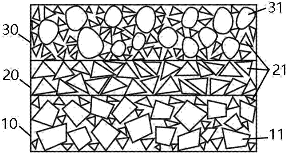
[0088] By separately preparing: the positive electrode layer mixed material, in which the mass ratio of active material lithium cobaltate, electrolyte LAGP, conductive carbon and binder PVDF is 7:3:0.5:0.5, and NMP is used as a solvent to prepare a slurry; the electrolyte layer is mixed The material, in which the mass ratio of electrolyte LAGP and binder PVDF is 90:10, and NMP is used as a solvent to prepare slurry. The positive electrode slurry was coated on the carrier Al with a thickness of 10 μm and a coating thickness of 100 μm. Then the electrolyte slurry was coated on the carrier Cu, and the spray thickness was 150 μm. The positive electrode layer and the electrolyte layer are overlapped to form a stacking layer, and the obtained stacking layer is subjected to mechanical wave heating treatment for a heating time of 6 s and a pressure of 1 MPa to obtain a positive electrode-electrolyte sheet. The microstructure of the positive electrode-electrolyte sheet is as Image 6 T...

example 2

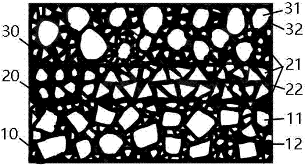
[0090] The positive electrode layer mixed material, the electrolyte layer mixed material and the negative electrode layer mixed material are mixed separately by a vibration mixing method. The mixed material of the positive electrode layer includes lithium iron phosphate, the electrolyte LATP, the binder PVA, and the conductive additive super P; the mixed material of the electrolyte layer includes the electrolyte LATP and the binder PVA; the mixed material of the negative electrode layer includes the negative active material graphite, adhesive Binding agent CMC. Three uniformly mixed materials were sprayed on the current collector Al in a large area, and Cu was added as the negative current collector. The stacked structure obtained by spraying is heated by ultrasonic for 0.1s and 1 MPa to obtain the battery cell. The microstructure of the battery cell is like Figure 8 The SEM photo is shown. Due to the short processing time, the particles are not completely melted, only a sma...

example 3-12

[0092] Table 7 below lists the material composition and rapid interface heating method of Examples 3-12, as well as the voltage range and first week efficiency of the resulting battery.

[0093] Table 7 Examples 3-12

[0094]

[0095] By comparing the results of Comparative Example 1 above with the results of Examples 1-12 according to the present invention, it can be found that, compared to the solid-state battery prepared by the long-term sintering method alone, the present invention uses the rapid interface heating method to control the particle interface. Including electrolyte particles, electrolyte and positive electrode particles, the interface between negative electrode and electrolyte particles is heated at a high temperature for a short time, which can improve the interface contact, while inhibiting the inter-diffusion of the interface and the formation of the inert layer, so as to improve the interface performance, thereby improving The cycle performance of solid-state ba...


PUM

PropertyMeasurementUnit
Thicknessaaaaaaaaaa

Abstract

The invention relates to a solid-state battery and a preparation method therefor. The preparation method for the solid-state battery comprises the steps of preparing a stacking structure, wherein the stacking structure at least comprises a positive electrode layer and a solid-state electrolyte layer arranged on the positive electrode layer; the positive electrode layer comprises positive electrode active material granules and solid-state electrolyte granules; and performing quick interface heating on the stacking structure to enable the interface of at least one kind of the positive electrode active material granules and the solid-state electrolyte granules in the positive electrode layer to be fused to generate an interface fused phase, so as to directly connect the positive electrode active material granules and the solid-state electrolyte granules.

Description

Technical field [0001] The present invention generally relates to the field of new energy sources, and more particularly, to a simple, rapid, and large-scale method for preparing solid-state batteries, and solid-state batteries prepared by the method. Background technique [0002] In recent years, the fast-developing electric vehicle and energy storage industries have put forward higher requirements for the energy density, cost, cycle characteristics and safety characteristics of secondary batteries represented by lithium-ion batteries and lead-acid batteries. Take lithium-ion batteries as an example. Conventional lithium-ion batteries mainly use graphite anodes. The theoretical capacity of graphite anodes is 372mAh / g. At present, major domestic graphite anode manufacturers, such as Jiangxi Zichen and Shenzhen Beiterui, have achieved 365mAh. The capacity of / g is close to the limit of theoretical capacity. In order to achieve higher energy density and power density, people began...

Claims


Application Information

Patent Timeline
IPC IPC(8): H01M10/058
CPCH01M10/058Y02E60/10Y02P70/50
Inventor 黄杰邱纪亮杨琪卢嘉泽李泓
Owner INST OF PHYSICS - CHINESE ACAD OF SCI
Why Eureka
Try Eureka