Denitrification filter backflushing precise control device and operating method
A control device and backwashing technology, which is applied in the direction of chemical instruments and methods, filtration treatment, special treatment goals, etc., can solve the problem that it is difficult to ensure the scientific denitrification of the backwashing strategy and the rapid recovery of the filtration function, shorten the operation period of the filter tank, increase the Operating costs and other issues, to solve the backwash intensity and time is difficult to grasp and judge, restore denitrification and filtration functions, and reduce energy consumption
- Summary
- Abstract
- Description
- Claims
- Application Information
AI Technical Summary
Problems solved by technology
Method used
Image
Examples
Embodiment 1
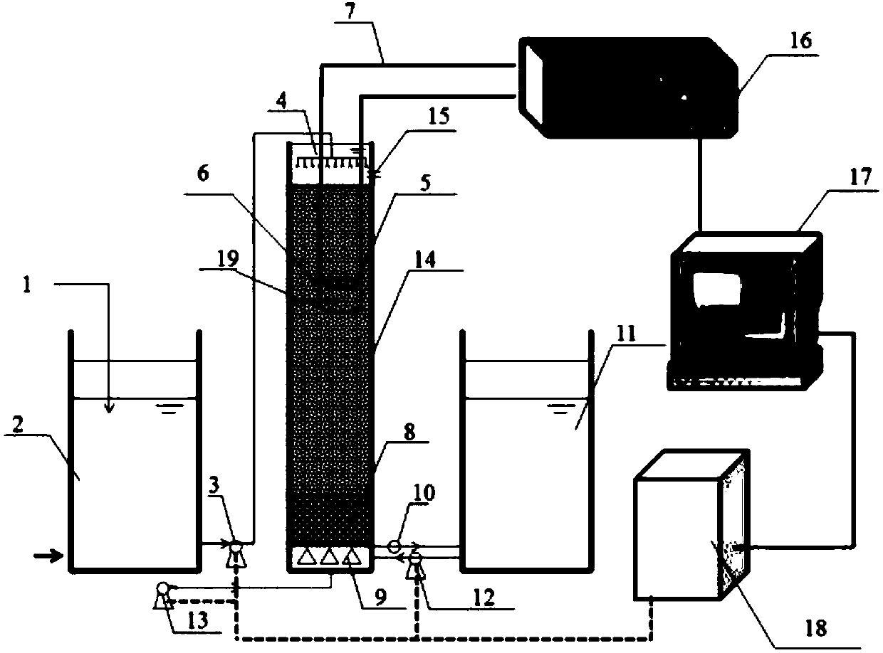
[0032] Such as figure 1 A denitrification filter backwash precision control device shown in the figure includes a regulating tank 2, a denitrification filter 14, a clear water tank 11, a dosing device 1, an inlet pump 3, an in-situ detection sensor 6, an electrode cable 7, Backwash water inlet pump 12, backwash air pump 13, backwash water outlet 15, electrochemical workstation 16, computer 17, process controller 18; Pipeline connection, the dosing pipe of the dosing device 1 extends into the regulating pool 2, the denitrification filter 14 is a columnar structure, and the denitrification filter 14 includes a uniform water distributor 4, The filter material layer 5, the support layer 8 and the filter brick 9, and the uniform water distributor 4 are composed of graded water distribution devices, which are respectively composed of the water inlet main pipe, the main pipe, the branch pipe and the water distributor with uniform distribution of water distribution holes; the filter m...
Embodiment 2
[0041] The difference from Example 1 is that the in-situ detection sensor 6 is placed in the quartz sand packing layer, located 40 cm below the surface of the quartz sand filter material, and is a hollow cylinder with a diameter of 7 cm, a height of 7 cm, and a thickness of 0.5 cm. It is high-density polyethylene or polypropylene, and the in-situ detection sensor 6 is pasted with a platinum sheet on the inner wall, which is 2.5cm long and 2.5cm wide. The platinum sheet is connected to the electrochemical workstation 16 through a wire 7, and the electrochemical workstation 16 passes The connection line is connected with the computer 17, and the computer 17 is equipped with control software corresponding to the electrochemical workstation 16.
[0042] Hydraulic load 1m 3 / m 2 h, plus COD / N=3-4, the water quality parameters of sewage treated by this device and method change: influent COD 72-95mg / L, TN 18-26mg / L, TP 0.68-0.81mg / L, SS 19- 34mg / L, NO 3 -N 16-20mg / L; effluent COD ...
Embodiment 3
[0044] With embodiment 1, the difference is that the in-situ detection sensor 6 is placed in the quartz sand filler layer, located 50 cm below the surface of the quartz sand filter material, and is a hollow cylinder with a diameter of 10 cm, a height of 10 cm, and a thickness of 0.6 cm. The material is high-density polyethylene or polypropylene, and the in-situ detection sensor 6 is pasted with a platinum sheet on the inner wall, which is 3 cm long and 3 cm wide. The platinum sheet is connected to the electrochemical workstation 16 through a wire 7, and the electrochemical workstation 16 is connected to The line is connected with the computer 17, and the computer 17 is equipped with control software corresponding to the electrochemical workstation 16.
[0045] Hydraulic load 1m 3 / m 2 h, plus COD / N=5-6, the water quality parameters of sewage treated by this device and method change: influent COD 104-141mg / L, TN 18-26mg / L, TP 0.68-0.81mg / L, SS 19- 34mg / L, NO 3 -N 16-20mg / L; ...
PUM
| Property | Measurement | Unit |
|---|---|---|
| particle diameter | aaaaa | aaaaa |
| porosity | aaaaa | aaaaa |
Abstract
Description
Claims
Application Information
 - R&D
- Intellectual Property
- Life Sciences
- Materials
- Tech Scout
- Unparalleled Data Quality
- Higher Quality Content
- 60% Fewer Hallucinations
Browse by: Latest US Patents, China's latest patents, Technical Efficacy Thesaurus, Application Domain, Technology Topic, Popular Technical Reports.
© 2025 PatSnap. All rights reserved.Legal|Privacy policy|Modern Slavery Act Transparency Statement|Sitemap|About US| Contact US: help@patsnap.com


