A photocatalytic reaction device

A photocatalytic reaction and reactor technology, which is applied in chemical instruments and methods, chemical/physical processes, oxidized water/sewage treatment, etc., can solve the problem of slow catalyst surface mass transfer efficiency, difficult catalyst recovery, limited separation rate, etc. To achieve the effect of enhancing the ability of ultraviolet photooxidation, promoting the ultraviolet photooxidation reaction, and expanding the scope of treatment

Active Publication Date: 2021-07-09
CHINA PETROLEUM & CHEM CORP +1
View PDF15 Cites 0 Cited by
  • Summary
  • Abstract
  • Description
  • Claims
  • Application Information

AI Technical Summary

Problems solved by technology

Suspension-type photocatalytic reactors generally use micron or nanometer catalyst particles, which have a large specific surface area and many active sites for photocatalysis, so they have high photocatalytic efficiency; the light source is usually set in a suspension containing catalyst and water to be treated. In the turbid liquid, the light penetration is poor and the attenuation is fast, resulting in a low utilization rate of light; the suspended powder catalyst is difficult to separate and recover
The supported photocatalytic reactor mainly solves the problem of catalyst separation and recovery, but because a part of the active sites of the photocatalyst is used to combine with the carrier, the number of active sites available for the supported photocatalyst is greatly reduced, resulting in a decrease in catalytic activity and pollution. The mass transfer efficiency on the surface of the catalyst slows down, and the light utilization rate decreases
[0004] The patent document with the publication number CN 100427414 C discloses a magnetic separation coupling airlift suspension photocatalytic water treatment method and its device. The above device does not use the ozone generated by the ultraviolet lamp in the quartz lamp sleeve to reduce the mineralization effect. energy efficiency
Moreover, the above-mentioned device simply uses the air lift and the water flow generated by the guide tube to prevent the precipitation of the photocatalyst, and the bottom of the device has a square dead corner, which may cause the catalyst to precipitate and reduce the utilization of the catalyst.
In addition, the above-mentioned device is provided with a funnel-shaped magnetic separation device, and a ring magnet is added below the cone of the funnel. This magnetic separation device has a simple structure, and the separation effect on difficult-to-separate micron or submicron catalyst or adsorbent particles is not significant, and Difficult to recover the catalyst from the system
[0005] The patent document with the publication number CN 201962095 U discloses a magnetically separable photocatalytic sewage treatment device. The device simply uses the water flow generated by the blast to prevent the precipitation of the photocatalyst, and there is a part at the bottom of the device where no air flow passes through, and there is catalyst precipitation. Possibility of reducing catalyst utilization
In addition, a cylindrical magnetic separation device is located below the cylindrical photoreactor, which relies on gravity settling, which limits the separation rate and makes it difficult to recover the catalyst from the system
[0006] The patent document whose publication number is CN 204661484 U discloses an aeration type catalytic reaction device with magnetic separation function. Possibility of catalyst precipitation, which reduces catalyst utilization
In addition, the disclosed magnetic field generating device is placed directly under the reaction tank, and the reaction tank itself is a magnetic separation device. This design requires a large area to install magnets, and it is difficult to recover the catalyst from the system, because this design cannot concentrate the catalyst.
[0007] The photocatalytic devices disclosed in the above-mentioned patents do not have agitators in them, and rely solely on the airflow to stir the wastewater, so it is impossible to generate sufficient shear force and effectively prevent the photocatalyst from agglomerating in the wastewater
[0008] In addition, the photocatalytic reaction devices disclosed in the patent documents of CN101497488A, CN101555082A, CN102557311A, CN1508073A, CN102258971A, CN102241450A, CN1587085A, and CN102180553A cannot utilize the ozone produced by ultraviolet lamps, and do not completely solve the problem of catalyst precipitation and photocatalyst agglomeration. , and there is a problem of low magnetic separation function

Method used


Image

  • A photocatalytic reaction device
  • A photocatalytic reaction device
  • A photocatalytic reaction device

Examples


Embodiment 1

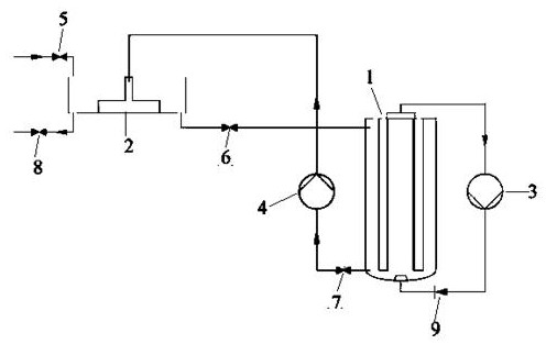
[0031] Such as Figure 1-5 As shown, when the present invention is not in use, the first valve 5, the second valve 6, the third valve 7 and the fourth valve 8 are all in closed state, and the electric control disk 23, the air pump 3 and the water pump 4 are not started. During use, a catalyst is placed in the water tank 21, and then the first valve 5 is opened to allow the untreated primary waste water to enter the water tank 21 of the magnetic separator 2. After the primary waste water enters the water tank 21, the mechanical stirrer and the ultrasonic system are started, and the Under the combined action of the agitator and the ultrasonic system, the magnetic catalyst can be effectively dispersed and suspended in the primary wastewater, so that the primary wastewater is mixed with the catalyst.

[0032] Then open the second valve 6, so that the primary waste water mixed with the catalyst enters the still body 11 and the kettle cover 12 to form the accommodation chamber 111 a...

Embodiment 2

[0042] With reference to the settings in Example 1, only the gas flow rate in the air pump 3 was changed to 4L / min, and the ozone concentration generated was 78ppm. Finally, the COD concentration in the tertiary wastewater was measured to be 14mg / L, and the COD removal rate was 93%.

Embodiment 3

[0044] Referring to the settings in Example 1, only the gas flow rate in the air pump 3 was changed to 2L / min, and the generated ozone concentration was 53ppm. Finally, the COD concentration in the tertiary wastewater was measured to be 37mg / L, and the COD removal rate was 82%.


PUM

PropertyMeasurementUnit
wavelengthaaaaaaaaaa

Abstract

The invention discloses a photocatalytic reaction device, which includes a reaction kettle, which includes a kettle body, a kettle cover, an air pump with a controllable gas flow rate, a check valve, a microbubble generator for generating microbubbles, a plurality of first A pipe, a stirrer and a plurality of ultraviolet lamps fixed on the lid of the kettle, the lid and the body of the kettle form an accommodation cavity; the stirrer and the ultraviolet lamp vertically pass through the lid of the kettle and extend into the accommodation chamber; each ultraviolet lamp has The ultraviolet light source of vacuum ultraviolet rays with a wavelength of less than 200nm and the ultraviolet rays with a wavelength greater than 200nm, and the lamp cover that can pass through the vacuum ultraviolet rays and ultraviolet rays. The top of the lamp cover of each ultraviolet lamp is connected with the external environment; A pipeline, the other end of the first pipeline communicates with the air inlet of the air pump outside the accommodation chamber; the microbubble generator is arranged at the bottom of the accommodation chamber, and the air outlet of the air pump communicates with the microbubble generator. The invention can integrate vacuum ultraviolet light oxidation technology, ultraviolet light oxidation technology and ozone oxidation technology into one.

Description

technical field [0001] The invention belongs to the field of wastewater treatment, and in particular relates to a photocatalytic reaction device. Background technique [0002] In recent years, photocatalytic oxidation technology, as an advanced oxidation technology, has attracted increasing attention from scholars at home and abroad. Almost all organic substances can be completely mineralized into simple inorganic substances such as carbon dioxide and water under the action of photocatalysis. Among the photocatalytic oxidants, the metal oxide semiconductor titanium dioxide is the most typical. Among the technologies reported at home and abroad to use titanium oxide to catalyze the oxidation of organic pollutants, titanium oxide in the dispersed phase and titanium oxide in the stationary phase are mainly used. Photocatalytic oxidation, which uses semiconductor photocatalysts to oxidize organic matter, has a good oxidative decomposition effect on highly toxic and difficult-t...

Claims


Application Information

Patent Timeline
Patent Type & Authority Patents(China)
IPC IPC(8): B01J8/20C02F1/32C02F1/72C02F101/30
CPCB01J8/20C02F1/32C02F1/725C02F1/727C02F2101/30
Inventor 李建涛司徒伟梁耀彰李芳李宝忠
Owner CHINA PETROLEUM & CHEM CORP
Why Eureka
Try Eureka