Natural gas smoke waste heat complete heat recovery device

A flue gas waste heat and total heat recovery technology, applied in the field of emission devices, can solve the problems of large-capacity recovery equipment, bulky, unsuitable for energy-saving renovation of established power plants, and unused flue gas waste heat, etc., to reduce heating costs , stable performance, and the effect of improving the heat-to-electricity ratio

Pending Publication Date: 2018-06-08
苏桐梅
View PDF2 Cites 12 Cited by
  • Summary
  • Abstract
  • Description
  • Claims
  • Application Information

AI Technical Summary

Problems solved by technology

Chinese patent "201110110470.x" "Central Heating System Using Absorption Heat Pump to Recover Flue Gas Waste Heat" discloses a centralized heating system that uses absorption heat pump to recover flue gas waste heat from gas boilers and gas turbines. The absorption heat pump requires Using gas or high-temperature steam as the driving source of the heat pump in the gas-fired cogeneration system requires corresponding transformation of the re...

Method used


Image

  • Natural gas smoke waste heat complete heat recovery device
  • Natural gas smoke waste heat complete heat recovery device
  • Natural gas smoke waste heat complete heat recovery device

Examples


Embodiment 1

[0057] Embodiment 1: (attach Figure 5 )

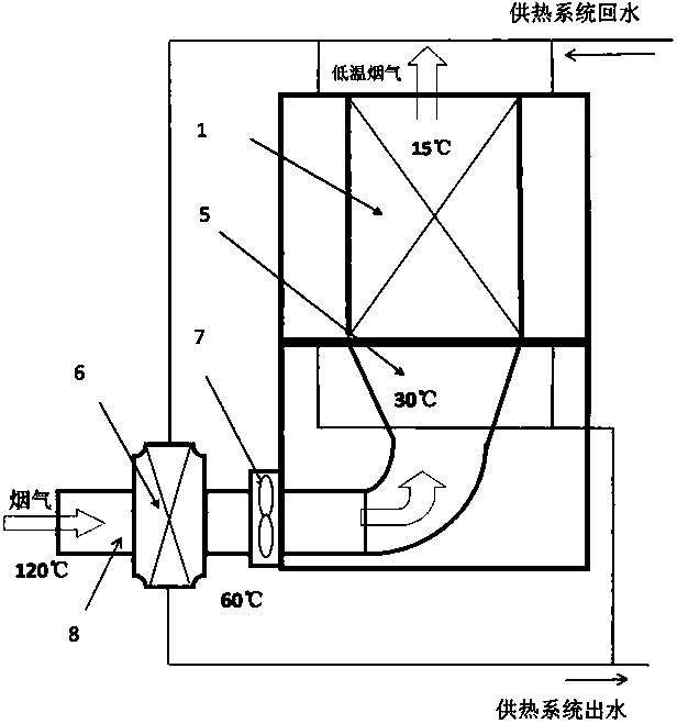
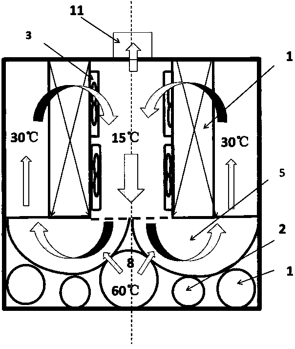
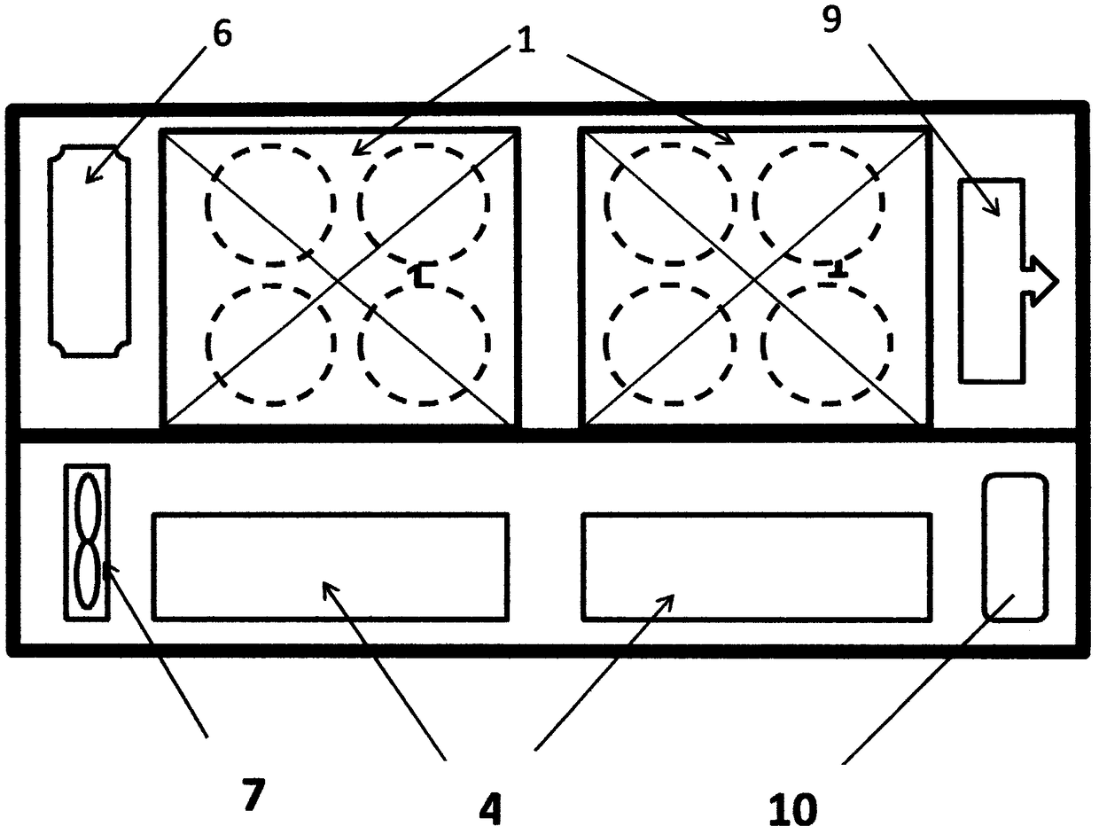
[0058] This embodiment is a typical implementation method of the technology of the present invention. It is applicable to the waste heat recovery of flue gas in the built gas-steam combined cycle heat and power cogeneration power plant, without any modification inside the power plant. On the flue gas side, it is only necessary to connect a high-temperature flue to the chimney to lead the flue gas at 90°C into the gas-water heat exchanger to cool down to medium-temperature flue gas (about 60°C), and introduce skid-mounted gas flue gas waste heat through the fan for full heat recovery In the device, the flue gas enters the mixing cooler through the flue to drop to 30±5°C, then enters the heat pump evaporator to drop to 15±5°C, and is discharged to the atmosphere from the low-temperature flue. The circulating return water of the heating system enters the condenser for heat exchange and rises in temperature, and then is pressurized by t...

Embodiment 2

[0059] Embodiment 2: (attach Figure 6 )

[0060] This embodiment is a typical implementation method of the technology of the present invention. It is suitable for the flue gas waste heat recovery of the built gas-steam combined cycle cogeneration power plant. There is no space and area to install the waste heat recovery device inside and outside the power plant. It is necessary to add an equipment platform to the space above the chimney of the power plant or boiler room to recover the waste heat. The device is mounted on the platform. On the flue gas side, it is only necessary to connect a high-temperature flue to the chimney to lead the flue gas at 90°C into the gas-water heat exchanger to cool down to medium-temperature flue gas (about 60°C), and introduce the gas flue gas waste heat total heat recovery device through the fan, and the flue gas The gas passes through the flue in the device and enters the mixing cooler to drop to 30±5°C, and then enters the heat pump evapor...

Embodiment 3

[0062] This embodiment is an implementation method of the technology of the present invention. It is suitable for the energy-saving transformation of the built-in gas combustion equipment whose flue gas temperature is lower than 70°C. In recent years, some gas-fired boilers have undergone energy-saving transformation and installed a first-level flue gas waste heat recovery device. The exhaust gas temperature is lower than 70°C, and some sensible heat and most latent heat are still wasted without recovery. In this scheme, the flue gas connected to the fan is installed on the original chimney, and the flue gas below 70°C is introduced into the skid-mounted gas flue gas waste heat total heat recovery device through the fan. ±5°C, and then enter the heat pump evaporator to drop to 15±5°C, and discharge to the atmosphere from the low-temperature flue. The circulating return water of the heating system enters the condenser for heat exchange and rises in temperature, and then is pre...


PUM


Abstract

The invention provides a natural gas smoke waste heat complete heat recovery device, belongs to the technical field of energy, and particularly relates to a technology for completely recovering smokewaste heat emitted by fuel gas burning devices (boilers, direct-fired machines, gas engines, gas turbines and the like). Aiming at the status-quo that the heat energy utilization rate of a current natural gas boiler is low, a three-grade cooling two-grade heat exchanging technological process is adopted, cascaded cooling is conducted on smoke through a heat exchanger and a heat pump, particularlylatent heat for vaporization in the smoke is recovered and reused, the smoke emission temperature of a natural gas boiler is decreased to be the temperature the same as the natural gas entering the boiler, and complete utilization of the heat energy of the natural gas is truly achieved. In the processes of smoke cooling and heat energy recovering, a great deal of condensed water is recovered, partof sulfide and nitric oxide in the smoke is dissolved in the water, and thus emission of pollutants is reduced. When the natural gas smoke and waste heat complete heat recovery device is applied to combined heat and power generation power plants, less electric energy can be consumed in the heating period, the heating area can be increased by 30% or above, and the consumption amount of heating fuel gas can be reduced by 10-15%.

Description

technical field [0001] The invention belongs to the field of energy technology, and particularly relates to a method for recovering the waste heat of flue gas discharged from a gas combustion device (boiler, direct-fired engine, gas internal combustion engine, gas turbine, etc.) A device for the discharge of pollutants. Background technique [0002] Although natural gas belongs to fossil energy, since the direct products of its combustion are carbon dioxide and water, it has little impact on the environment under the condition of low-nitrogen combustion, and it is a clean fuel for improving air quality, so its thermal energy should be All transformations are used. However, the present situation of natural gas thermal energy utilization rate and flue gas recovery efficiency is not satisfactory, and the thermal energy utilization rate of heating boilers is generally lower than 80% (in terms of high calorific value). The most advanced combined heat and power technology does n...

Claims


Application Information

Patent Timeline
IPC IPC(8): F25B30/06F23J15/06F22D11/06F24D3/18
CPCF22D11/06F23J15/06F24D3/18F25B30/06Y02E20/30
Inventor 李崇兴
Owner 苏桐梅
Why Eureka
Try Eureka